Chapter 5: AMBA APB Overview
APB (Advanced Peripheral Bus) is the bus protocol in ARM's AMBA (Advanced Microcontroller Bus Architecture) standard for low-speed, low-power peripherals. It connects to the AHB (high-speed bus) through an AHB2APB bridge.
AMBA APB Protocol
AMBA Family
- AHB (Advanced High-performance Bus): high-speed system bus for the CPU, memory, and so on
- APB (Advanced Peripheral Bus): low-speed peripherals such as UART, timers, and GPIO
- AXI (Advanced eXtensible Interface): high performance with out-of-order and multi-outstanding transactions
APB characteristics
- Non-pipelined: just a simple setup + access phase
- Low-power, low-performance
- APB slaves are lightweight to implement → well suited to peripherals
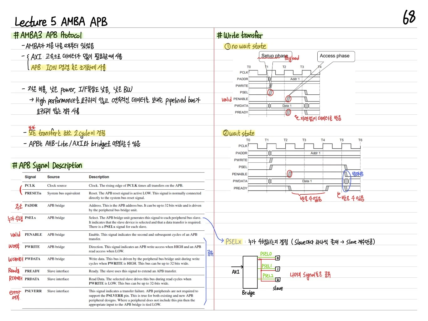
Signals
- PCLK: bus clock
- PRESETn: active-low reset
- PSEL: slave select (driven by the master)
- PENABLE: high in the second cycle (access phase)
- PADDR: address (32-bit)
- PWRITE: 1=write, 0=read
- PWDATA: master → slave data (write)
- PRDATA: slave → master data (read)
- PREADY: slave ready signal (controls wait states)
- PSLVERR: error response
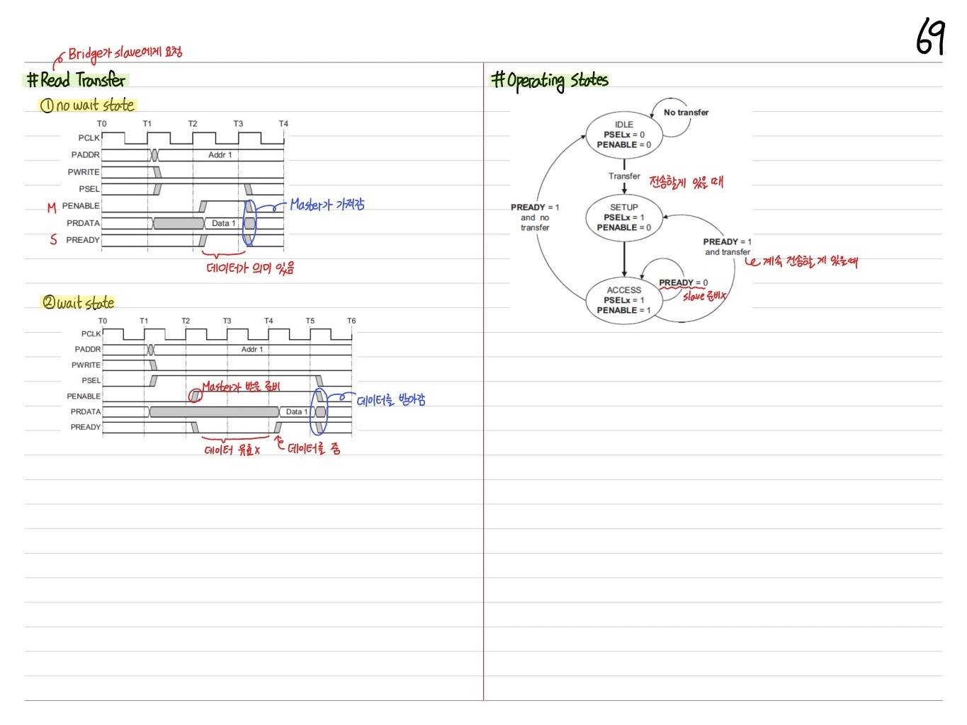
APB Read Transfer
① No Wait State
T0  T1  T2  T3  T4
PCLK   __/\__/\__/\__/\__
PADDR  __[Addr 1]________
PWRITE __[_______ 0 ]____
PSEL   __/‾‾‾‾‾‾\____
PENABLE ____/‾‾‾\____     ← Master takes it
PRDATA ______[Data 1]____  ← Data is meaningful
PREADY ______/‾‾‾‾\____- T1: Setup (PSEL=1, PENABLE=0)
- T2: Access (PENABLE=1) → the slave prepares the data
- T3: The master samples PRDATA → transfer complete
② With Wait State
T0  T1  T2  T3  T4  T5  T6
PCLK   __/\__/\__/\__/\__/\__/\__
PADDR  __[____ Addr 1 _______]____
PSEL   __/‾‾‾‾‾‾‾‾‾‾‾‾‾‾‾‾\____
PENABLE ____/‾‾‾‾‾‾‾‾‾‾‾‾\____  ← Master ready to receive
PRDATA ________[___ Data 1 __]__  ← Data not valid → slave provides data
PREADY ____________/‾‾‾‾‾\____ ← Master takes the data- If the slave is not ready, it holds PREADY=0
- When PREADY=1, the data is valid → the master samples it
Operating States (APB Slave FSM)
An APB slave is an FSM with three states, IDLE → SETUP → ACCESS:
       [IDLE]  (PSELx=0, PENABLE=0)
         │  ↑
         │  │ No transfer
         │  │
    Transfer (when there is something to send)
         │
         ▼
      [SETUP]  (PSELx=1, PENABLE=0)
         │
         ▼
      [ACCESS]  (PSELx=1, PENABLE=1)
         │  ↑
         │  │ PREADY=0 (slave not ready)
         │  │
     PREADY=1 and transfer (when there is more to send)
         │
         ▼
[SETUP] (or [IDLE] if no transfer)- IDLE: no transfer
- SETUP: the master starts a transaction (asserts PSEL)
- ACCESS: the actual data transfer (PENABLE=1), waiting on PREADY
AHB to APB Bridge
A bridge sits between the high-speed AHB and the low-speed APB:
- AHB master → bridge → APB slave
- The bridge decodes the address → selects the corresponding APB slave
- It inserts wait states to absorb the clock domain/speed difference
Write Transfer
Symmetric with read. PWRITE=1, and the write data is driven on PWDATA.
T0  T1  T2  T3
PCLK     _/\_/\_/\_/\_
PADDR    _[Addr]______
PWRITE   _[__1_]______
PSEL     _/‾‾‾\______
PENABLE  ___/‾‾\______
PWDATA   _[__Data__]__
PREADY   ___/‾‾‾\____
APB vs AHB
| Property | AHB | APB |
|---|---|---|
| Pipeline | Pipelined address + data phases | Non-pipelined (2 cycles) |
| Burst | Supported (INCR, WRAP) | Not supported |
| Multi-master | Supported (arbiter) | Single master (bridge) |
| Performance | High | Low |
| Use | CPU, DMA, memory | UART, timers, GPIO |
Summary
| Concept | Key point |
|---|---|
| APB setup phase | PSEL=1, PENABLE=0 |
| APB access phase | PSEL=1, PENABLE=1, completed by PREADY |
| Wait state | Holding PREADY=0 delays the transaction |
| AHB2APB bridge | Master = AHB, slaves = APB peripherals |
| FSM: IDLE → SETUP → ACCESS | 2-cycle basic transaction |
Because APB is simple and low-power, every peripheral in ARM Cortex-M SoCs (UART, SPI, I2C, timers, GPIO, etc.) is implemented as an APB slave.