1. Problem and Key Features
Vending machines are one of the most common conveniences in everyday life. Most vending machines are well stocked, but machines in low-traffic places are often empty. That is because in areas with little demand, the effort spent on restocking is large relative to the revenue. So I came up with an IoT vending machine whose stock can be managed through an online database without anyone having to go and check it in person.
Remote places also lack CCTV and security staff, so items sometimes get stolen from vending machines. Adding a feature that sounds a siren and notifies the operator through the online database helps guard against this.
- Implementing the vending machine as an IoT device lets you see from outside when it has run out of stock. This reduces the manpower spent constantly checking stock.
- Checking the machine's revenue to date helps plan future investment (product choice, machine location, and so on).
- Preventing theft from the machine means it can be used even in areas with little CCTV or security.
- When something goes wrong with the machine, the built-in operator call button provides a fallback.
2. Hardware
1) Parts used
Raspberry Pi, 180-degree servo motor, 360-degree servo motor, buzzer, 3 tact switches, 3 proximity sensors, 2 LEDs, Firebase data storage
2) Top side
The vending machine is divided into a left part that holds the main system and a right part that handles dispensing. The dispensing section has a lid that opens so items can be restocked. Figure 1 shows the top side.
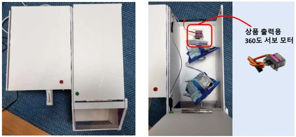
Figure 1. Top side of the vending machine
The dispensing section uses a 360-degree servo motor to dispense items. When the motor turns, a wire coil inside rotates and pushes the product out. This can be seen in Figure 2.
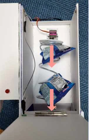
Figure 2. How products are dispensed
3) Front side
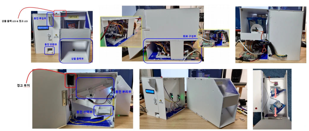
Figures 3 and 4 are photos of the front of the vending machine. The front has an LCD module, 3 buttons, an infrared sensor module, 2 LEDs, a coin slot, a product outlet, and a coin return. Each one works as follows.
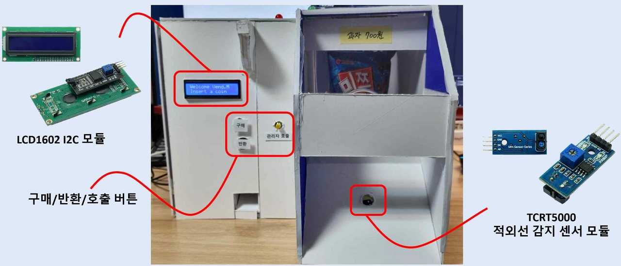
Figure 3. Front of the vending machine 1
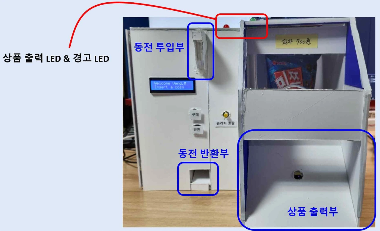
Figure 4. Front of the vending machine 2
LCD module
The LCD module displays two lines of text. The module used in this project is an LCD 1602 I2C module, which solves the problem of older LCD modules using too many GPIO pins by using the I2C protocol. The I2C protocol consists of two signal lines, SDA (Serial Data) and SCL (Serial Clock). Its advantage is that up to 127 devices can be connected with just two signal lines, and its maximum speed is 400kHz.
In this project, the LCD module shows the state of the vending machine, such as the amount of coins inserted and whether a purchase has completed.
Purchase/return/call buttons
These are the buttons the user presses: the purchase button to buy, the return button to get inserted coins back, and the operator call button to call the operator when something goes wrong with the machine.
Infrared sensor module
The vending machine contains 3 TCRT5000 infrared sensor modules in total. One of them is used at the product outlet on the front. Figure 5 shows the specs of the TCRT5000 infrared sensor module. Used with its analog output, it can measure distance with infrared; used with its digital output, as in this project, it can detect whether an object is in front of the sensor.

Figure 5. Specs of the TCRT5000 infrared sensor module
The infrared module at the product outlet has two roles. First, when a product is dispensed, the 360-degree servo motor rotates, and the sensor stops the servo once the product has fully come out; it detects that the product has been dispensed. Second, it provides theft prevention. When no product is being dispensed, it detects someone reaching into the outlet to steal items.
Dispensing LED and warning LED
The dispensing LED shows visually that a purchase went through and the product is being dispensed. The warning LED is used to warn the user when theft is suspected.
Coin slot, coin return, product outlet
Where coins go in, where coins are returned, and where products come out.
4) Left side
Figures 6 and 7 are photos of the left side of the vending machine. It has a door that opens so coins can be collected and the machine can be maintained. It also holds the warning buzzer, which can warn users about theft.
The left side is divided into a coin sorting section and a coin selection section. Each one works as follows.
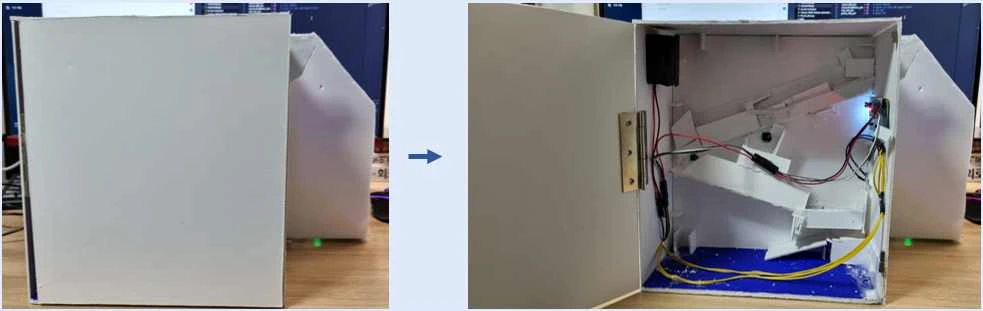
Figure 6. Left side of the vending machine 1
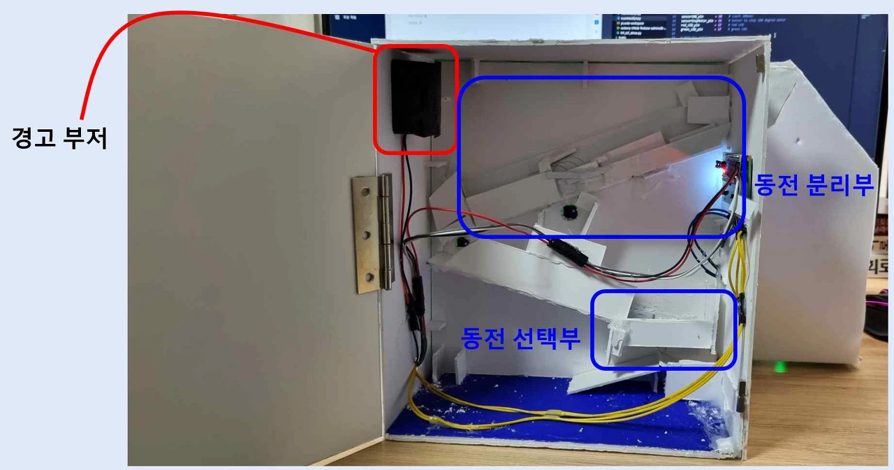
Figure 7. Left side of the vending machine 2
Coin sorting section
The coin sorting section separates the 500-won and 100-won coins coming in from the coin slot. Figure 8 shows how it works. Coins from the slot roll down a rail. As they do, the 500-won and 1000-won coins pick up speed. The 100-won coins, having picked up speed, pass over the hole that 500-won coins drop through and fall under the 100-won sensor. The 500-won coins, on the other hand, hit the purple piece, lose speed, and fall under the 500-won sensor.
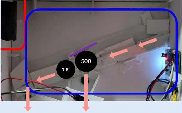
Figure 8. How coins are sorted
Coin selection section
Coins sorted by the section above pass the sensors and collect in the coin selection section. Figure 9 explains how coins are kept and returned. The coin selection section has a single flap that can be set to left, right, or center. The flap is driven by the 180-degree servo motor, located on the "6) Middle panel." When the servo tilts the flap to the left, coins go into the machine; when it tilts to the right, coins are sent to the coin return.
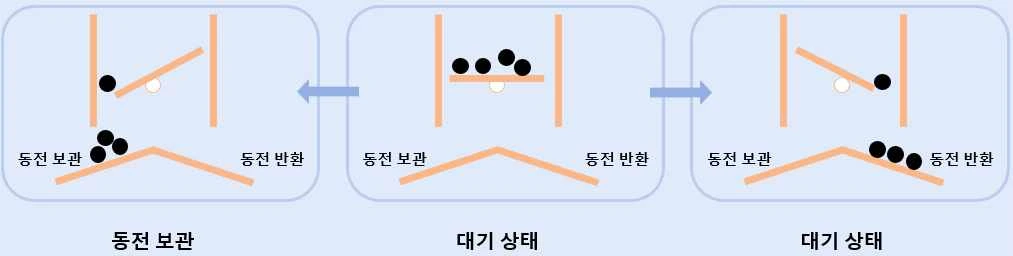
Figure 9. How coins are kept and returned
5) Right side
Figure 10 shows the right side of the vending machine. All of the machine's pins are wired to the Raspberry Pi so it can control them.
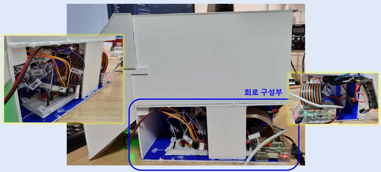
Figure 10. Right side of the vending machine
Parts that use 5V and parts that use 3.3V were wired separately. The 5V supply came from an external power source, and the 3.3V supply came from the Raspberry Pi itself. For easy wiring, I used a Raspberry Pi GPIO T-board and a breadboard. Figure 11 is the completed circuit.
6) Back side
The back side is laid out as shown in Figure 12.
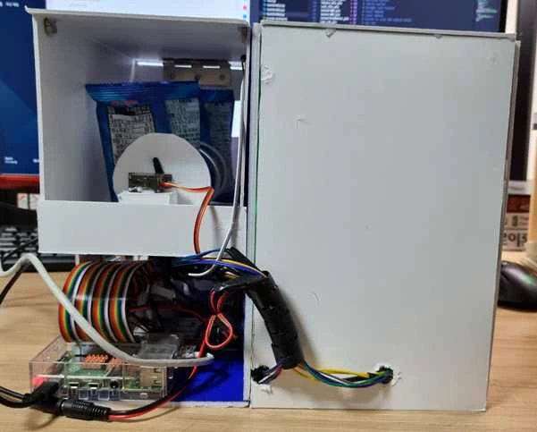
Figure 12. Back of the vending machine
7) Middle panel
The middle panel is laid out as shown in Figures 13 and 14. Magnets let the system section and the dispensing section be separated, which makes maintenance easier. The middle panel holds 2 infrared sensors and the 180-degree servo motor. Each one works as follows.
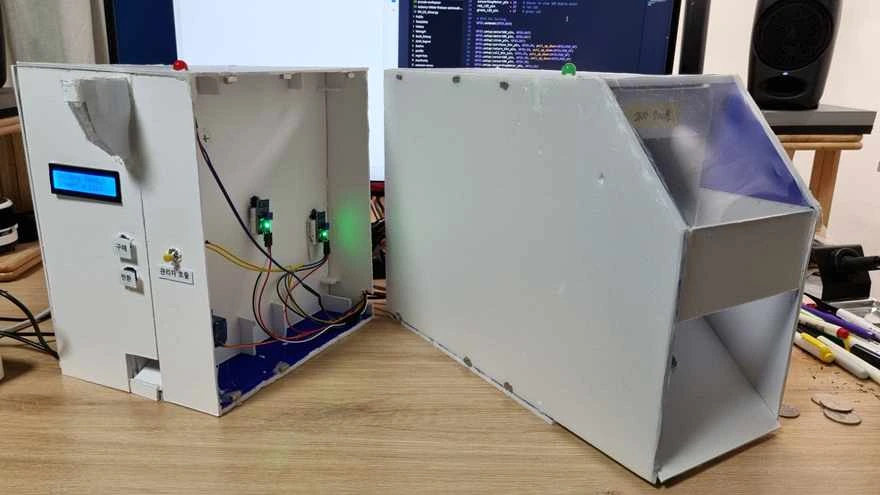
Figure 13. Middle panel of the vending machine 1
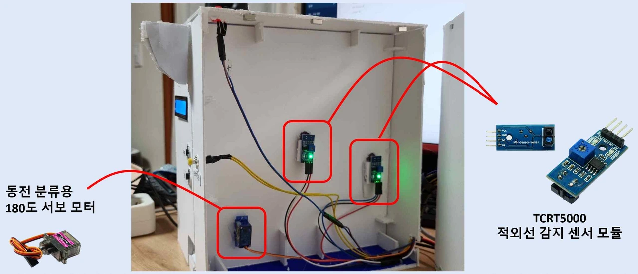
Figure 14. Middle panel of the vending machine 2
Infrared sensor module
Two of the vending machine's 3 infrared sensor modules are on the middle panel. Each sensor detects and counts the 100-won and 500-won coins sorted on the "4) Left side."
180-degree servo motor
Decides whether the coins collected in the coin selection section on the "4) Left side" are kept or returned. Depending on the motor angle, if the flap tilts left, coins go into the machine; if it tilts right, coins are sent to the coin return.
3. Software
The software was written in Python. I chose Python in order to use the Firebase data service. Firebase supports several languages, Python among them, but unfortunately not C. Since it uses the JSON format, it could still be done by writing functions that send and receive that format, but using Python, which already provides a library, was a big time saver, so I chose Python.
For external libraries, I used Python's time module, a module for Google's Firebase, a module for GPIO control, and a module that uses I2C to drive the LCD display. Apart from these external libraries, I wrote all the code myself.
External sensors are handled with interrupts, which lowers system power and avoids wasting CPU time. The main function is written as a polling loop so the system keeps running.
1) Importing external libraries
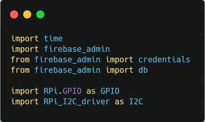
Figure 15. Importing external libraries
time module
The external libraries are imported as shown in Figure 15. time is imported to use the sleep() function, which adds a delay for a set amount of time.
firebase module
Firebase is an online database provided by Google. It supports real-time data, so data can be sent and received in real time. The Firebase module is organized as shown in Figure 16.
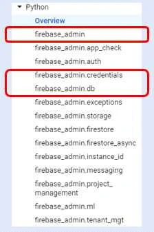
Figure 16. Structure of the firebase module
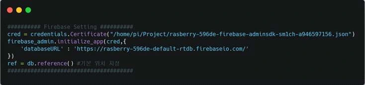
Figure 17. Firebase setup
First, credentials have to be loaded from credentials, part of the firebase module. This is because letting anyone access the Firebase database would be a security problem. The Cerificate() method is defined as shown in Figure 18. Reading it, it says that it loads credentials from a JSON file.
JSON is a format for exchanging data as attribute-value pairs. This JSON credentials file can be downloaded from Google Firebase and is different for every user.
I placed this file under the /home/pi/Project directory on the Raspberry Pi; passing it as the function argument returns the authenticated credentials, which I stored in the cred variable.
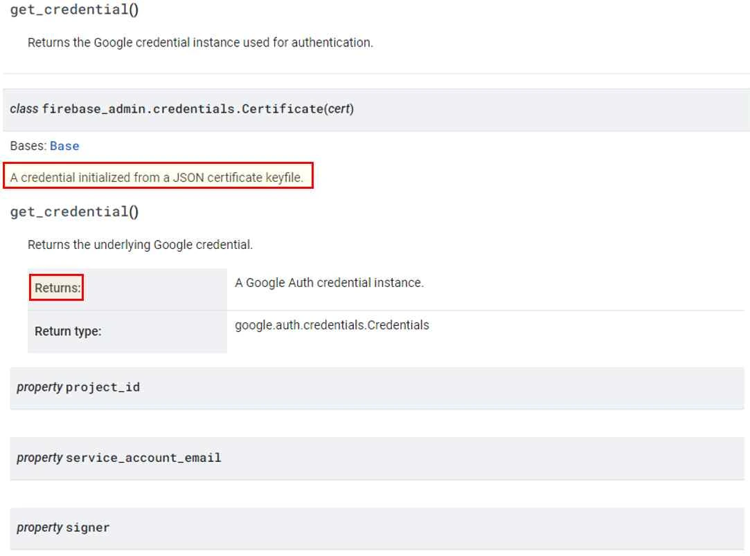
Figure 18. The Cerificate() method
The resulting cred is used to initialize Firebase. Figure 19 is the definition of the initialize_app() function that initializes Firebase. It takes cred and databaseURL. databaseURL is where the data is stored in Firebase. A Firebase database holds a lot of information, so this setting pins down the location you want.
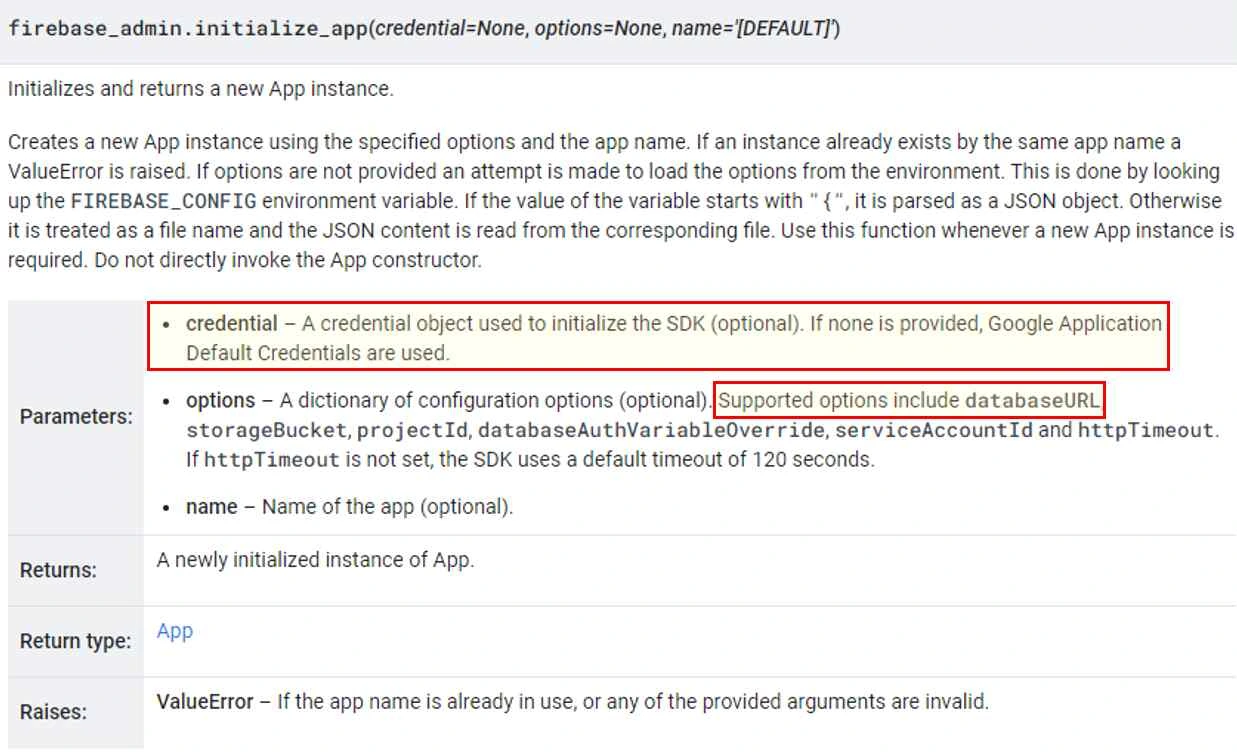
Figure 19. The initialize_app() method
The last step is to get a ref. Figure 20 is the definition of the db.reference() function for getting a reference from Firebase. All arguments are optional; if none are given, the database URL chosen above is used.
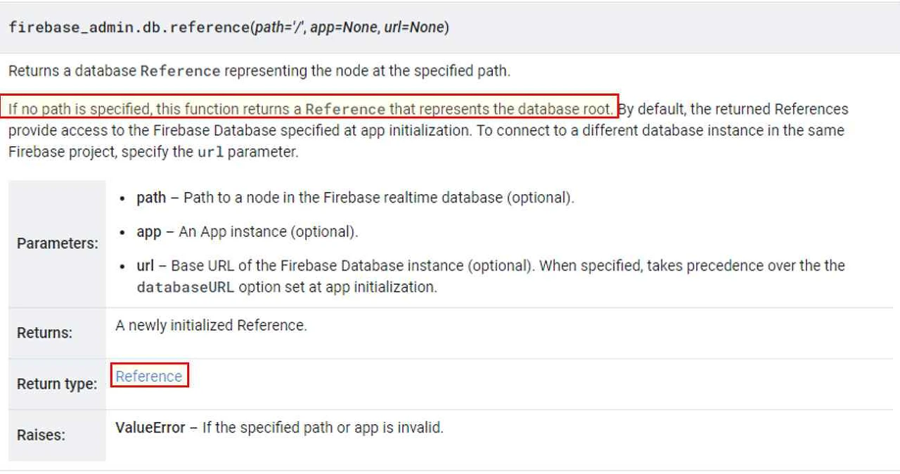
Figure 20. The db.reference() method
With that, the Firebase integration is complete, and the reference gives access to the real-time database. Figure 21 shows the database in Firebase, now linked with the Raspberry Pi.
Under vendingM, the database has Message, RaspUpdateSignal, earnCoin, and stock. Each one works as follows.
Message: a message from the Raspberry Pi, used to show text the operator must know about.
RaspUpdateSignal: a signal used to update the Raspberry Pi's data from Firebase.
earnCoin: shows the amount of money earned so far.
stock: shows the vending machine's stock.
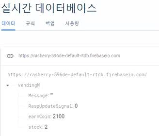
Figure 21. Firebase real-time database
LCD module
Imported to control the LCD over I2C.
GPIO module
Imported to control GPIO.
2) Pin setup
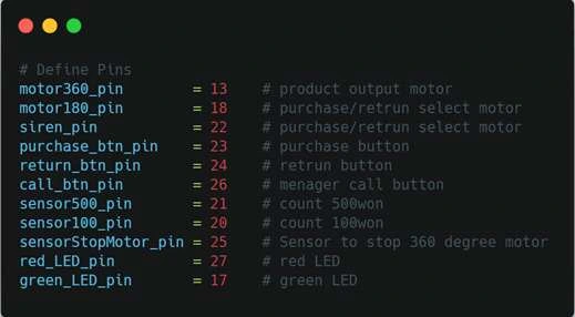
Figure 22. Pin setup
Figure 22 is the code that defines every pin used in the system.
Figure 23 is the code that sets the defined pins to input or output mode through the GPIO setup and assigns pull-up or pull-down mode.
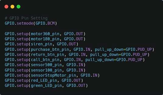
Figure 23. Pin and GPIO setup
Figure 24 shows the description of pull-up and pull-down mode in the GPIO.setup() function. Using the Raspberry Pi's internal pull-up and pull-down resistors has the advantage that you do not have to build the circuit yourself. The definition of each state can be seen in Figure 25.

Figure 24. Using the internal resistors
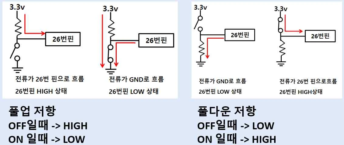
Figure 25. What pull-up and pull-down resistors are
3) Motor setup
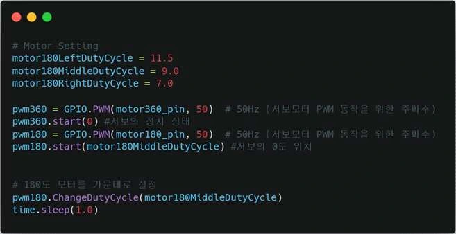
Figure 24. Motor setup
On the Raspberry Pi, motors can be controlled with a PWM signal. PWM control means controlling the width of a square wave. PWM control has two main parameters: frequency and duty ratio. Frequency is the number of oscillations per second, and duty ratio is the fraction of each period during which the signal is on. Figure 25 illustrates PWM control.
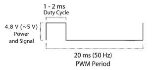
Figure 25. PWM control
The code in Figure 24 defines the duty values for the 180-degree motor. These values were found by experiment: 11.5 turns it left, 9.0 to center, and 7.0 right. Figure 26 shows the movement for each duty value.
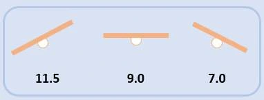
Figure 26. Movement of the 180-degree motor by duty value
For the servo motors to run on PWM, I passed a 50MHz frequency as the argument and declared the PWM 360 and PWM 180 objects, variables representing the 360-degree and 180-degree servo motors respectively. I then called each object's start() method to set its initial state.
The behavior of the 360-degree servo motor by duty value is shown in Figure 27. Unlike the 180-degree motor, the 360-degree motor stops at 0 and rotates continuously at 1.5.
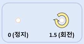
Figure 27. Movement of the 360-degree motor by duty value
ChangeDutyCycle() is the method that changes the PWM duty. The motor had been initialized with the same value, but it had not been given time to move. So, to be sure, I used ChangeDutyCycle() to set the motor to center. time.sleep() is a delay function that gives the motor time to move.
4) Defining the VendingMachine class
The VendingMachine class provides the vending machine's basic variables and functions. If the number of machines to manage grew, the code would get very long, so the class was made for code reuse and easier management.
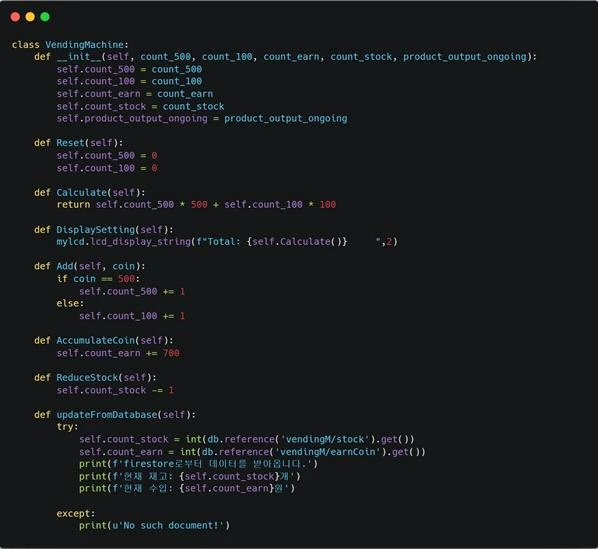
Figure 28. VendingMachine class
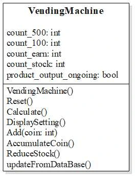
Figure 29. VendingMachine class diagram
Figure 29 shows the VendingMachine class as a class diagram. It has 5 built-in variables, which do the following:
count_500 : number of 500-won coins inserted into the machine
count_100 : number of 100-won coins inserted into the machine
count_earn : revenue so far
count_stock : number of items left in the machine
product_output_ongoing : whether the machine is currently dispensing a product
These variables are initialized when a VendingMachine object is created, as can be seen in the __init__ part of Figure 28.
The VendingMachine class has 7 methods, which do the following:
Reset() : resets the count of 100-won and 500-won coins inserted into the machine
Calculate() : computes and returns the amount currently inserted into the machine
DisplaySetting() : shows the inserted amount on the second line of the LCD
Add(coin) : adds to the count of 100-won and 500-won coins inserted into the machine
AccumulateCoin() : adds to the machine's revenue (the price is 700 won, so += 700)
ReduceStock() : decreases the stock by one
updateFromDatabase() : reads values from the database and updates the variables
The updateFromDatabase() method reads vendingM's stock and earnCoin's value from the database and updates count_stock and count_earn. It gets the values through the getter of db.reference() and converts them to int. Because it communicates with an external database, it needs exception handling. A try-catch block catches the exception so that the system does not fault when communication fails.
5) Creating the display object
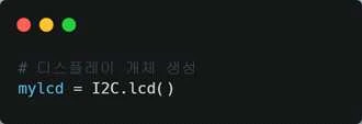
Figure 30. Creating the display object
This code creates an object of the LCD class from the external I2C library. The LCD class sends values to the LCD over I2C. The project uses only one method of the LCD class. Figure 31 is the definition of the LCD-display_string() method used in the project. It prints a string on the selected line, and I could also see that it sends the string one character at a time with a foreach loop. More detailed code can be found by opening the library.
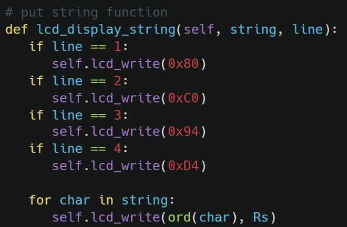
Figure 31. The LCD-display_string method of the LCD class
6) Writing the buttonPushed(sentence, m_control1) and initDisplay() functions
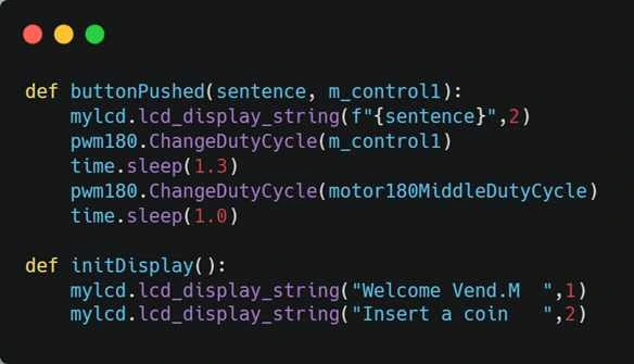
Figure 32. The buttonPushed(sentence, m_control1) and initDisplay() functions
The buttonPushed() function takes sentence and m_control1 as arguments, prints sentence on the second line of the LCD, moves the 180-degree motor to the position given by the m_control1 duty value, and then moves it back to center.
time.sleep() gives the motor time to move.
The initDisplay() function sets the initial display, the text shown when the system is not doing anything.
7) Initialization
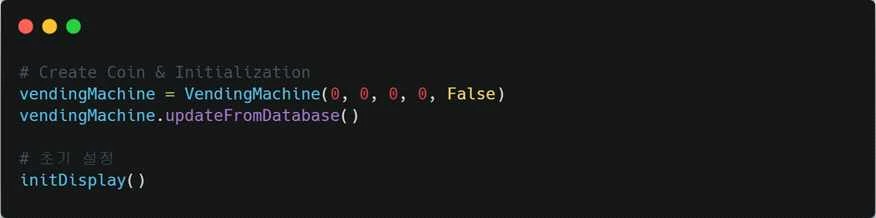
Figure 33. Initialization
Create a VendingMachine object with all member variables set to 0 or False. Then call the vendingMachine method updateFromDatabase() to read values from the database and initialize the variables.
Call initDisplay() to set the initial display.
8) Interrupt handlers - coins
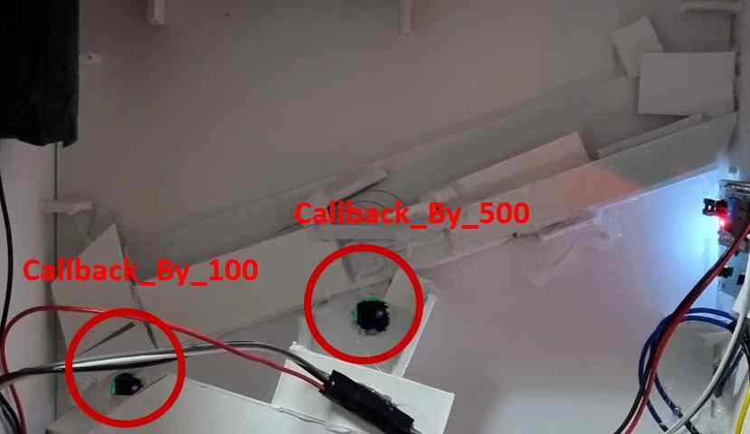
Figure 34. Coin interrupts
When an interrupt that requires counting coins occurs, as in Figure 34, the functions in Figure 35 run. The interrupts come from the infrared sensors.
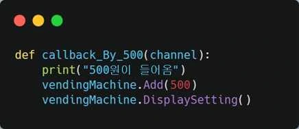
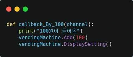
Figure 35. callback_By_500(channel), callback_By_100(channel)
The functions add to the count of 500-won and 100-won coins respectively and show the total amount inserted on the machine's LCD.
9) Interrupt handler - return
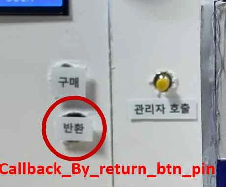
Figure 36. Return interrupt
When an interrupt that requires returning coins occurs, as in Figure 36, the function in Figure 37 runs. The interrupt comes from a button.
First, it resets the coins inserted into the machine so far. It then prints a return-complete message on the LCD, rotates the 180-degree motor to the return direction to return the coins, and resets the display.
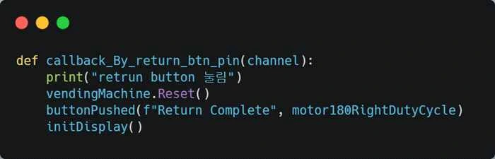
Figure 37. callback_By_return_btn_pin(channel)
10) Interrupt handler - purchase
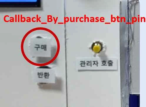
Figure 38. Purchase interrupt
When an interrupt that requires purchase handling occurs, as in Figure 38, the function in Figure 39 runs. The interrupt comes from a button.
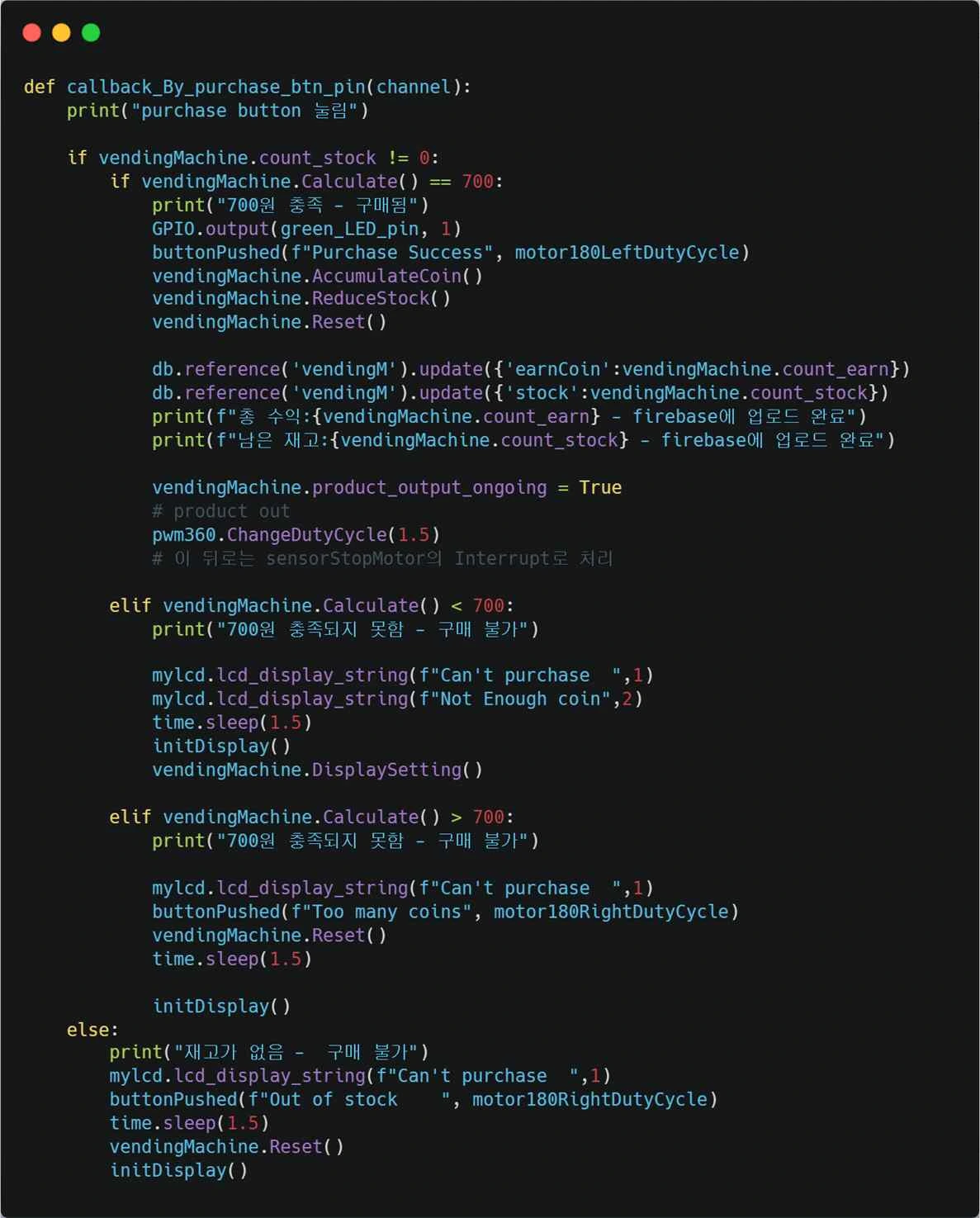
Figure 39. callback_By_purchase_btn_pin(channel)
Drawing the purchase interrupt as a flowchart and dividing it into parts gives Figure 40. Each part is described below.
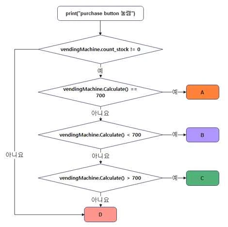
Figure 40. Flowchart of callback_By_purchase_btn_pin(channel)
A
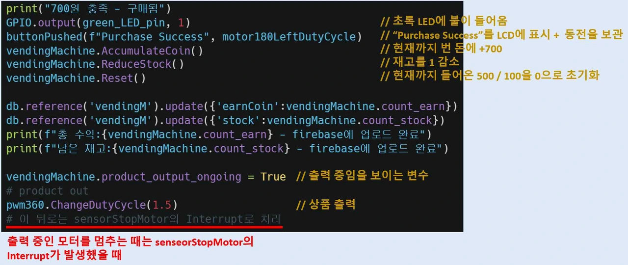
Figure 41. Part A of the callback_By_purchase_btn_pin(channel) flowchart
Part A runs when the machine's stock is not 0 and the user has inserted exactly 700 won. In other words, it runs when the purchase completes successfully.
It turns on the green LED, prints a purchase-complete message on the LCD, and rotates the 180-degree motor to the keep direction to keep the coins. It then adds 700 won to the earnings so far and decreases the stock by 1. It also resets the coins inserted into the machine so far.
After updating all of the machine's internal variables, it updates the data in the online database. Figure 42 shows the information being updated in the real-time database.
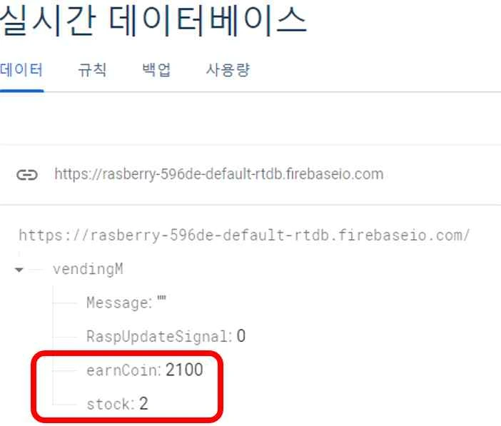
Figure 42. Real-time database update
Finally, the product has to be dispensed, and product_output_ongoing has to be set to True to mark that dispensing is in progress. This is because reaching into the outlet while product_output_ongoing is not True sets off the theft alarm. The handler sets the 360-degree motor's duty to 1.5 to start it rotating and finishes. Stopping the 360-degree motor is handled by the interrupt from the outlet's infrared sensor, which is explained in "12) Interrupt handler – motor stop and theft prevention."
B
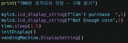
Figure 43. Part B of the callback_By_purchase_btn_pin(channel) flowchart
Part B runs when the machine's stock is not 0 and the user has inserted less than 700 won. In this case, it tells the user that not enough money was inserted and shows the amount inserted so far.
C
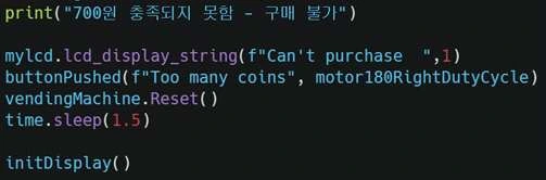
Figure 44. Part C of the callback_By_purchase_btn_pin(channel) flowchart
Part C runs when the machine's stock is not 0 and the user has inserted more than 700 won. In this case, it tells the user that too much money was inserted, returns the money inserted so far, and puts the machine back in its initial state.
D
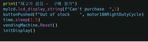
Figure 45. Part D of the callback_By_purchase_btn_pin(channel) flowchart
Part D runs when the machine is out of stock. In this case, it tells the user that it is out of stock, returns the money inserted so far, and puts the machine back in its initial state.
11) Interrupt handler – operator call
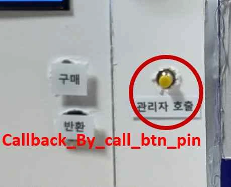
Figure 46. Operator call interrupt
When an interrupt that requires handling an operator call occurs, as in Figure 46, the function in Figure 47 runs. The interrupt comes from a button.
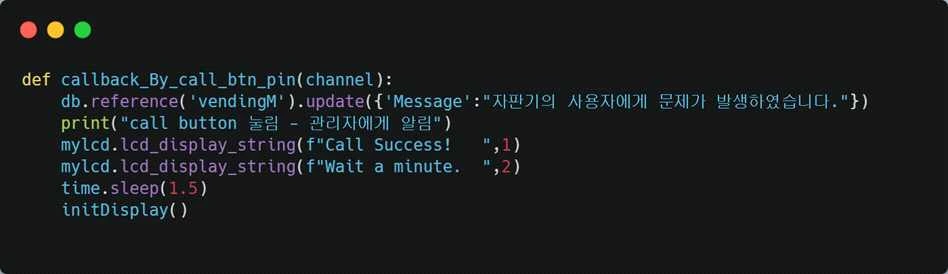
Figure 47. callback_By_call_btn_pin(channel)
This callback interrupt function runs when a user has a problem and presses the operator call button. As shown in Figure 48, it updates the database with a message telling the operator that something is wrong with the machine, tells the user via the LCD that the update succeeded, and then resets the LCD.
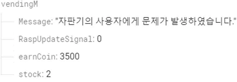
Figure 48. Real-time data (operator call)
12) Interrupt handler – motor stop and theft prevention
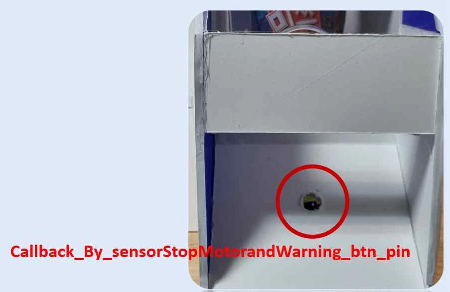
Figure 49. Motor stop and theft prevention interrupt
When an interrupt related to stopping the motor and preventing theft occurs, as in Figure 49, the function in Figure 50 runs. The interrupt comes from a button.
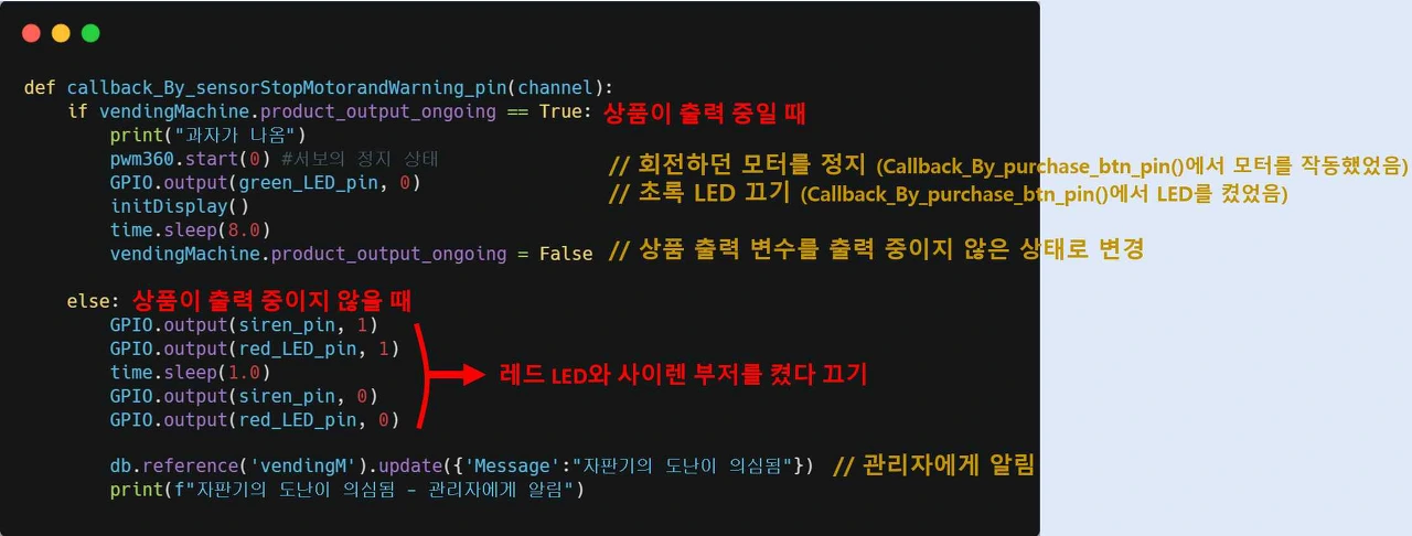
Figure 50. callback_By_sensorStopMotorandWarning_btn_pin(channel)
The callback_By_sensorStopMotorandWarning_btn_pin(channel) interrupt handler covers two cases: when product_output_ongoing is True (a product is being dispensed) and when product_output_ongoing is False (no product is being dispensed). Each case is handled as follows.
product_output_ongoing = True (a product is being dispensed)
When the product reaches the outlet, the infrared sensor detects it, and the servo motor must be stopped. The handler then turns off the green LED and sets product_output_ongoing back to False to mark that nothing is being dispensed.
product_output_ongoing = False (no product is being dispensed)
When nothing is being dispensed, reaching into the outlet must set off the theft alarm. For this, the buzzer and the red LED turn on for 1 second. Then, as shown in Figure 51, the handler updates the database with a message telling the operator that a theft problem has occurred at the machine.
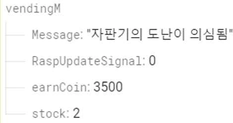
Figure 51. Real-time data (motor stop and theft prevention)
13) Interrupt setup

Figure 52. Interrupt setup
Sections 8) through 12) wrote the subroutine functions that handle each interrupt. These functions then have to be attached to pins using a function provided by the system. Figure 53 shows the definition of the add_event_detect function. It takes the pin number, the state setting, the subroutine function, and bouncetime as arguments. The state setting chooses which edge triggers the interrupt. When setting up the GPIO pins, I used pull-up resistors so that High is the default state, so I set it to trigger on the falling edge.
bouncetime was set to keep the interrupt handler from being called more than once, and I found and used a suitable value.
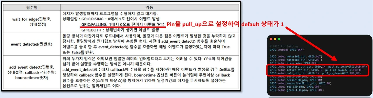
Figure 53. Interrupt edge
14) Implementing the main function
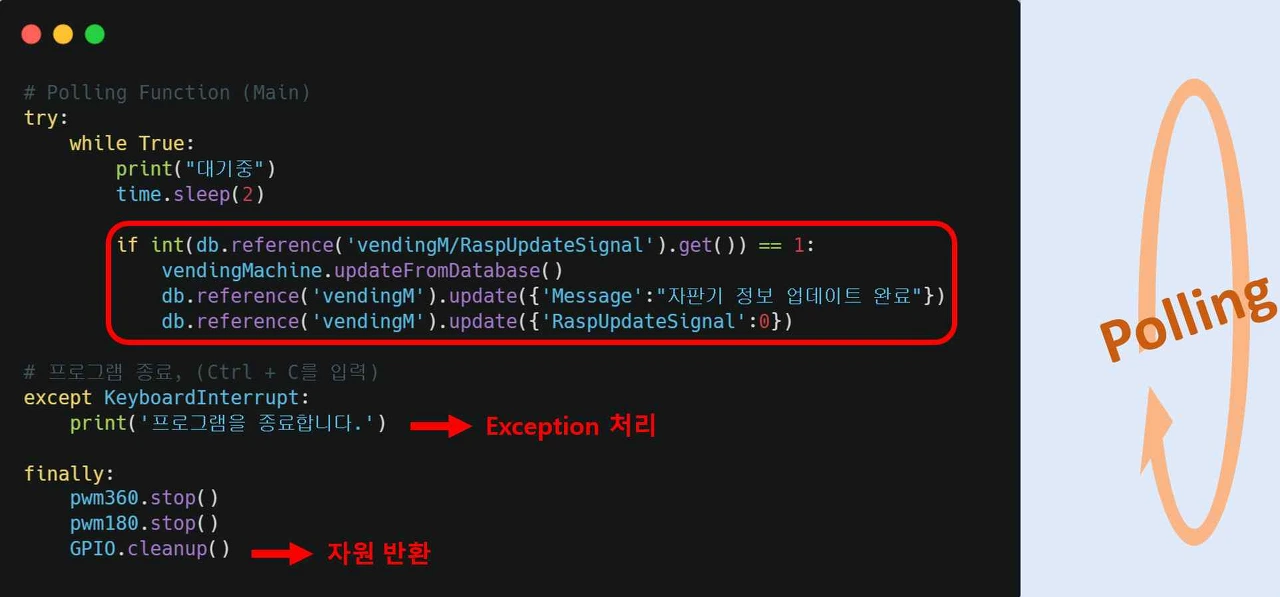
Figure 54. Main
Figure 54 is the main function. Python runs sequentially from top to bottom, so I declared all the needed functions first and then wrote the Main block, without giving the main function any particular name.
Exceptions are handled with a try-catch block. Since the program communicates online, exception handling is essential: if a value cannot be fetched from the server, the system would fault without it. I also handled the exception raised when Ctrl + C is pressed, to break out of the infinite loop.
The main loop's primary job is to wait. In addition, as shown in Figure 55, if RaspUpdateSignal is 1, it updates the Raspberry Pi's data from the Firebase database. To do this, it has to check every time whether RaspUpdateSignal in Firebase is 1. When all updates are done, the Raspberry Pi resets RaspUpdateSignal in Firebase to 0.
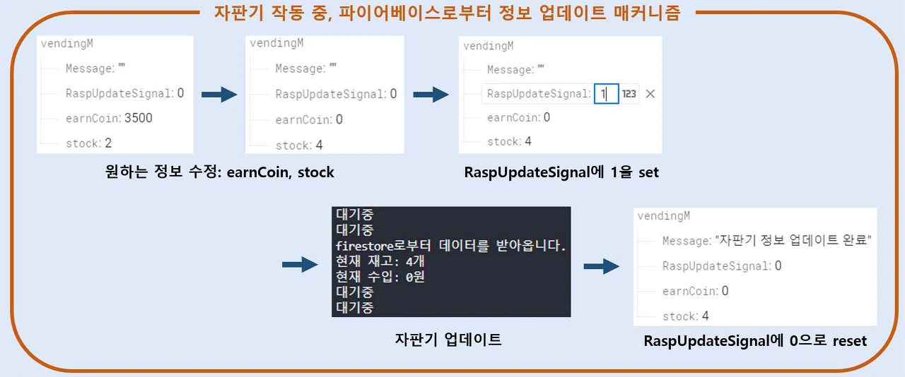
Figure 55. Mechanism for updating information from Firebase while the vending machine is running
Finally, a finally block releases resources. Its purpose is to shut the program down safely so that no problems occur when it is run again.
4. Reflections
For my embedded systems final project, I designed a vending machine using IoT. On top of the basic functions of a vending machine, I added several features that make it easier for an operator to manage. Along the way I used several sensors and a Raspberry Pi, with Python as the programming language. The core implementation relies on interrupts to improve system performance.
Working on this project deepened my understanding of interrupts and basic embedded systems, which I had learned in the fall semester.
(Note) All the code for this project is shared on GitHub.
(Note) There is a video of this project.
Sun Hong