Chapter 5: Cortex-M0 Overview
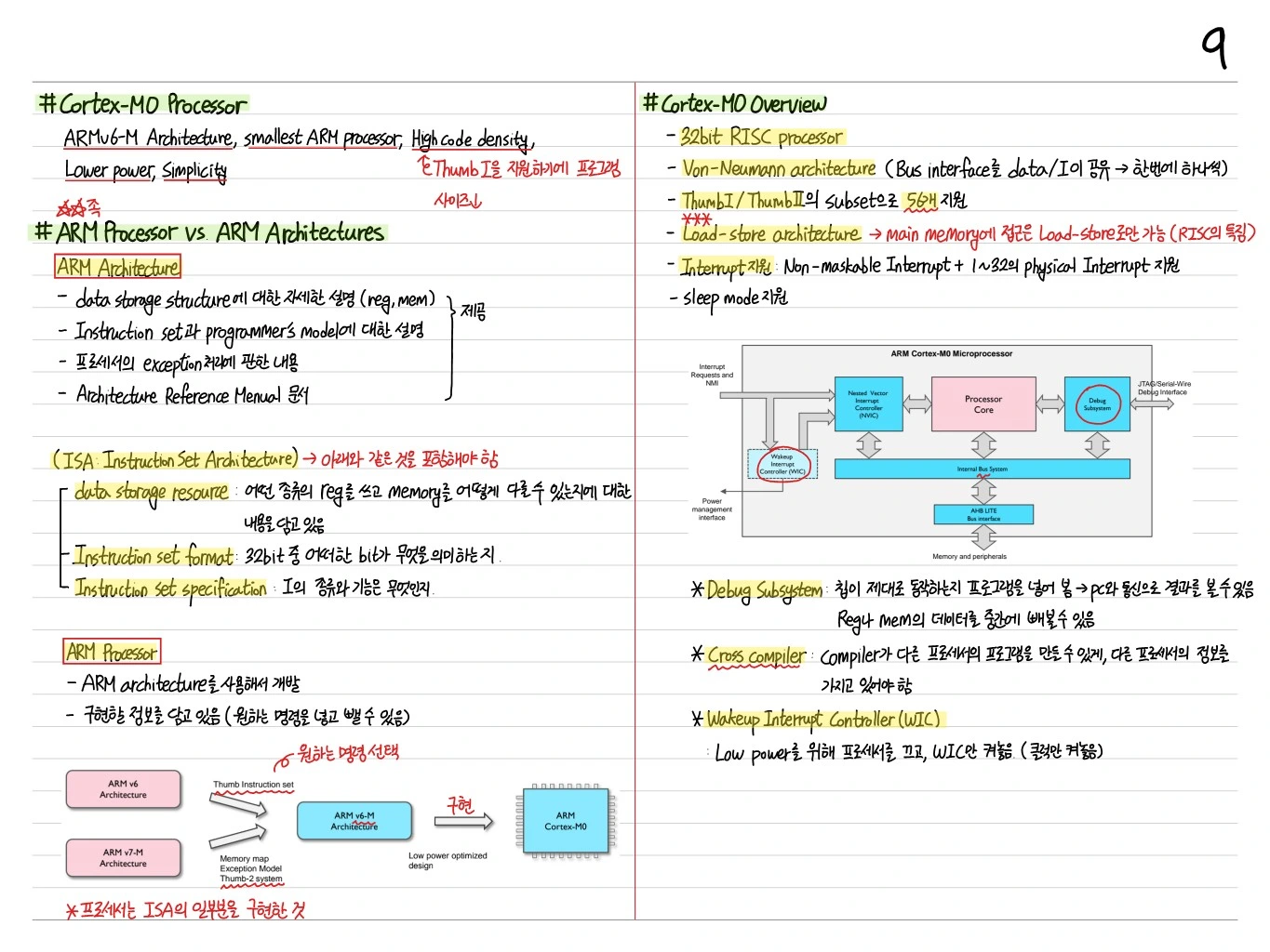
The ARM Cortex-M0 is a processor core based on the ARMv6-M architecture, built for ultra-low-power, ultra-small MCUs. With a 3-stage pipeline, Thumb-only instruction support, and a minimal NVIC, it is optimized for IoT devices, sensor nodes, and similar applications.
Cortex-M0 Features
- ARMv6-M architecture
- 3-stage pipeline: Fetch → Decode → Execute
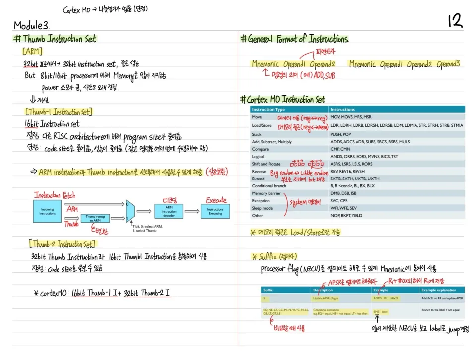
- Thumb instruction set (16-bit) + part of Thumb-2 (32-bit)
- ~11,000 gates (much smaller than the Cortex-M3)
- Ultra-low power at around ~12 μW/MHz
- Single-cycle multiplier (option)
- NVIC: Nested Vectored Interrupt Controller (up to 32 interrupts)
Cortex-M0 Structure
┌────────────────────────────────────┐
│   Cortex-M0 Processor Core          │
│  ┌──────────┐   ┌──────────────┐   │
│  │ Register │   │  NVIC        │   │
│  │ File     │   │ (up to 32)   │   │
│  └──────────┘   └──────────────┘   │
│  ┌──────────┐   ┌──────────────┐   │
│  │ ALU      │   │  Debug (SWD) │   │
│  └──────────┘   └──────────────┘   │
└────────────────────────────────────┘
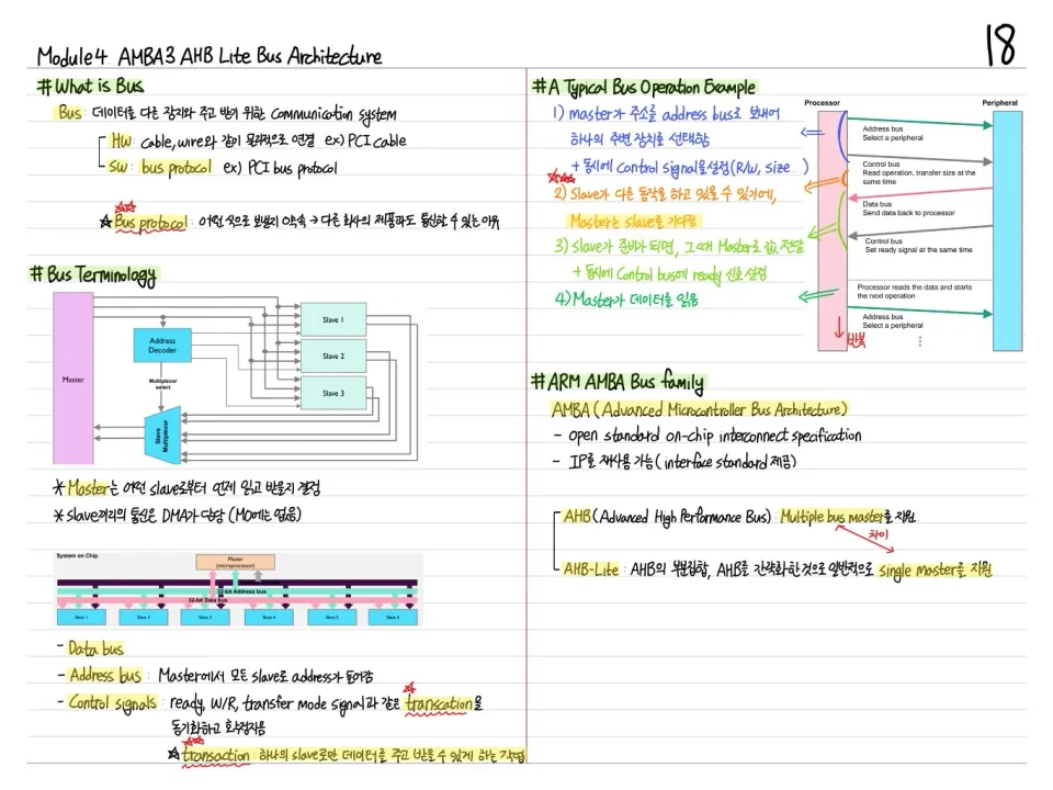
   AHB-lite bus → Memory, Peripherals
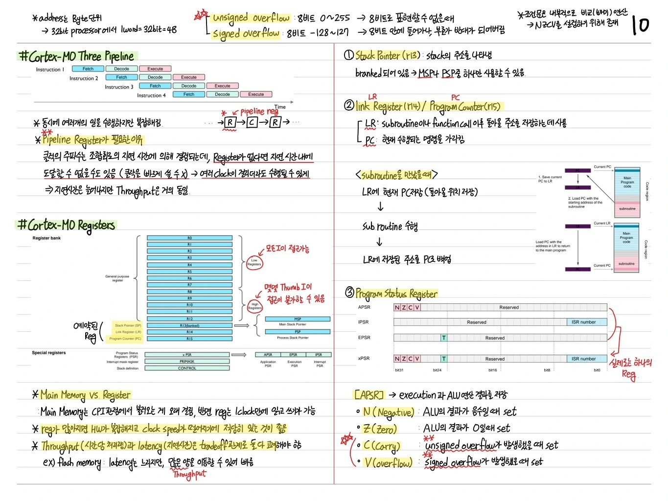
Register Set
- R0~R12: General-purpose registers
- R0~R7: Low registers (directly usable by all Thumb instructions)
- R8~R12: High registers (limited use, only in MOV/ADD)
- R13: Stack Pointer (MSP / PSP bank)
- R14: Link Register
- R15: Program Counter
- xPSR: Program Status Register
Operating Modes
- Thread mode: Runs normal programs
- Handler mode: Runs exception handlers
Privilege:
- Privileged: Full access to all features
- Unprivileged: Some restrictions (the Cortex-M0 is always Privileged)
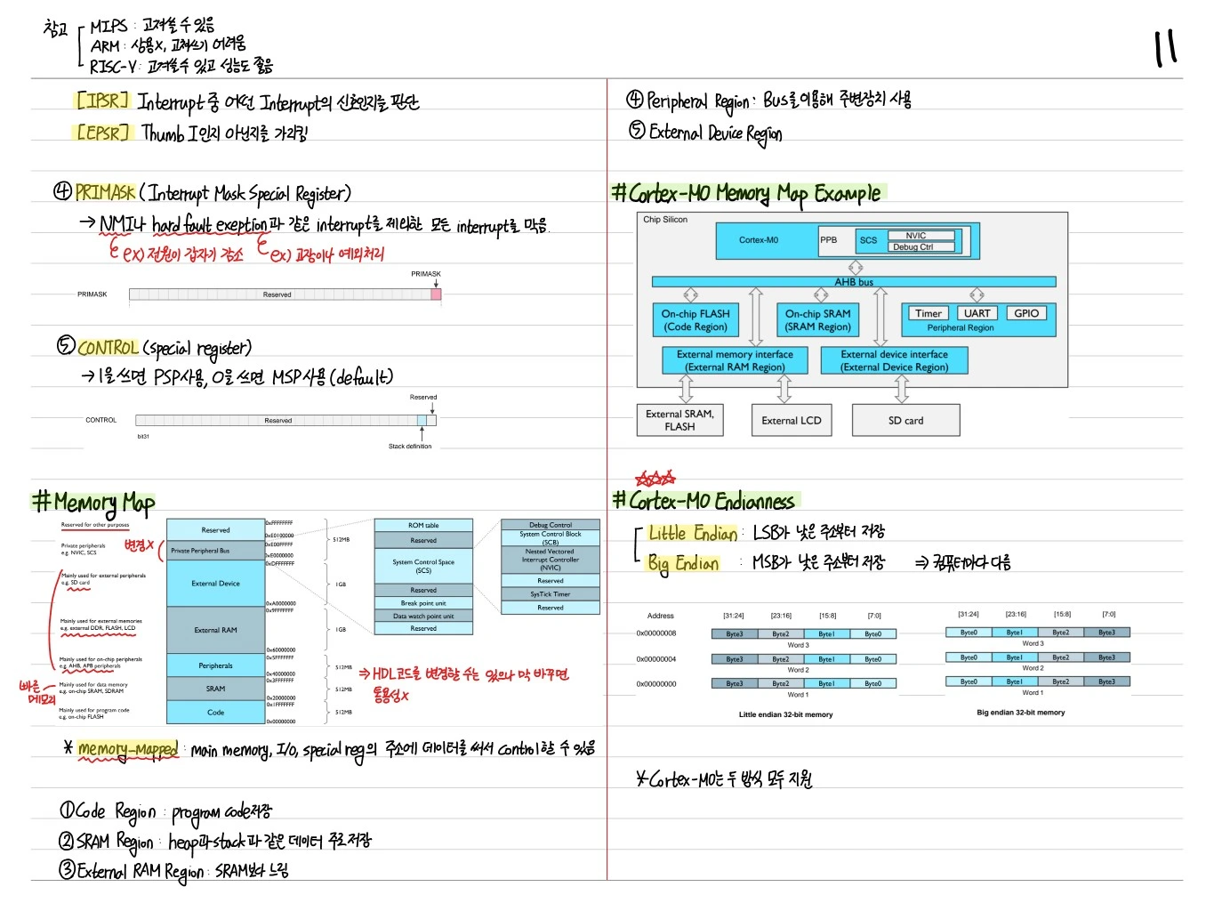
Memory Map
B = 4 GB virtual address space:
- 0x00000000 ~ 0x1FFFFFFF: Code (0.5 GB)
- 0x20000000 ~ 0x3FFFFFFF: SRAM
- 0x40000000 ~ 0x5FFFFFFF: Peripheral
- 0x60000000 ~ 0xDFFFFFFF: External RAM/Device
- 0xE0000000 ~ 0xE00FFFFF: Private Peripheral Bus (NVIC, SysTick, SCB)
Exception / Interrupt
- Vector table: Located at 0x00000000
- 15 system exceptions + up to 32 external IRQs
- Priority: Reset > NMI > HardFault > configurable
Thumb Instruction Set
The Cortex-M0 supports only Thumb instructions, plus a few 32-bit Thumb-2 instructions (BL, DSB, DMB, ISB, MRS, MSR, and so on).
- 16-bit instructions → smaller code size
- Branch, data processing, load/store, control flow
3-Stage Pipeline
[Fetch] → [Decode] → [Execute]- No branch prediction (introduced in the M3 and above)
- Branch taken → pipeline flush (1-cycle penalty)
SysTick Timer
A 24-bit down counter that provides a simple time base. Often used for the RTOS scheduler tick.
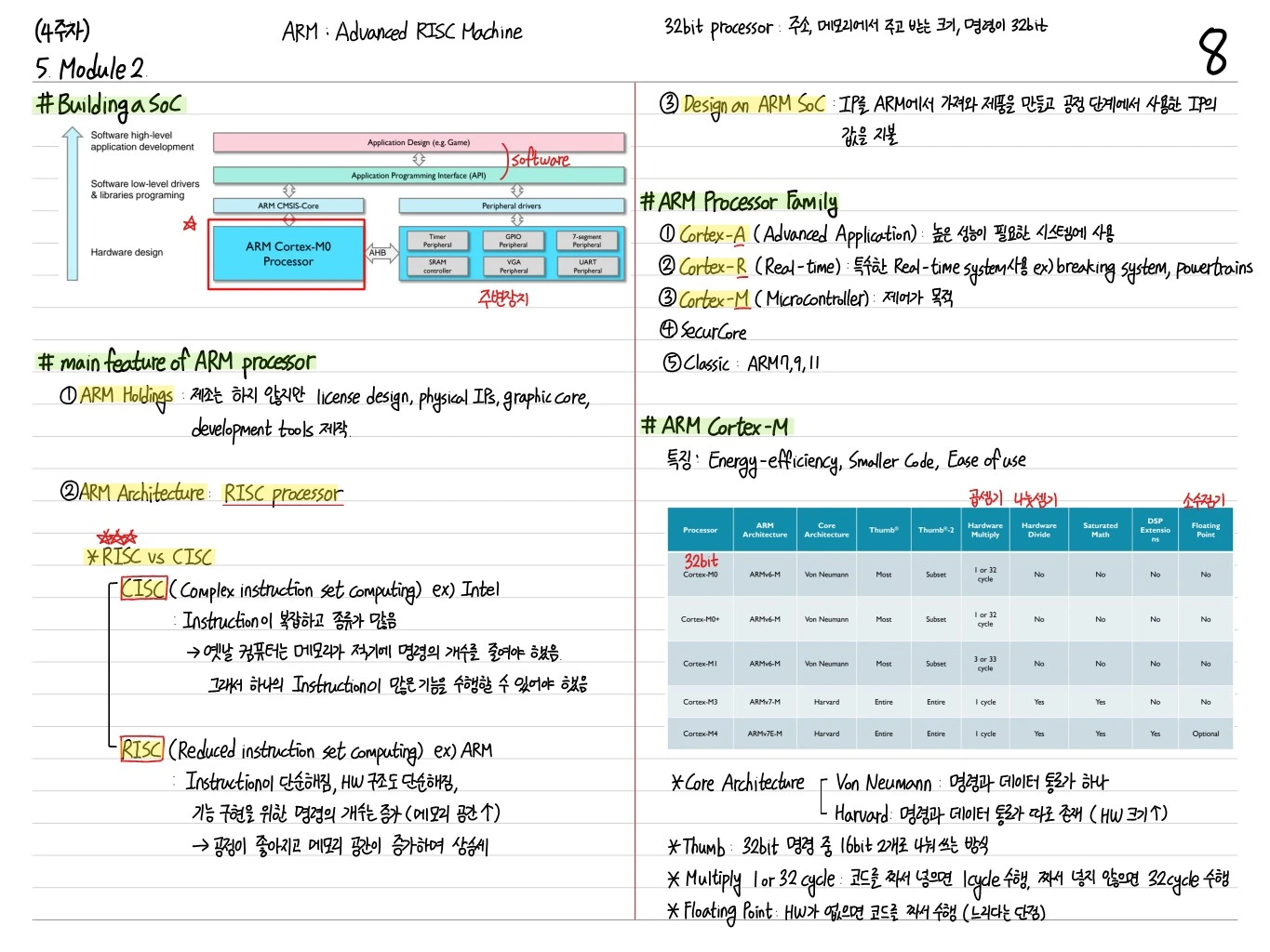
Cortex-M0 vs M3/M4
| Feature | M0 | M3 | M4 |
|---|---|---|---|
| ISA | ARMv6-M | ARMv7-M | ARMv7E-M |
| Thumb-2 | Limited | Full | Full + DSP |
| FPU | X | X | Option |
| Bit-band | X | O | O |
| MPU | X | Option | Option |
| Pipeline | 3-stage | 3-stage | 3-stage |
| Gates | ~11k | ~30k | ~50k |
| Use case | Sensors, IoT | General-purpose MCU | DSP, motor control |
Example Uses
- STM32F0 series
- NXP LPC1100 series
- Nordic nRF51 series
- Atmel SAM D20
Mainly used in battery-powered IoT devices, sensor nodes, and simple controllers.
Summary
| Item | Value |
|---|---|
| Arch | ARMv6-M |
| Pipeline | 3-stage |
| ISA | Thumb + subset of Thumb-2 |
| Register | R0~R15, xPSR, MSP/PSP |
| NVIC | Up to 32 IRQs |
| Memory | 4 GB linear address space |
| Use | Low-power IoT/sensor MCUs |
As the smallest and cheapest ARM core, the Cortex-M0 led the move from 8-bit to 32-bit in the MCU market.