Chapter 4: ARM Assembly Programming Overview
Covers the basic syntax of ARM assembly and the instructions needed for real programming: immediate operations, shifted register operands, addressing modes, branches, subroutines, and more.
Basic Structure of ARM Assembly
[label] instruction [operands] [; comment]- Label: Names a line of code so it can serve as a jump target
- Instruction: ARM mnemonic
- Operands: Mostly registers, immediates, and labels
- Comment: Starts with
;
General Features
General characteristics of ARM assembly.
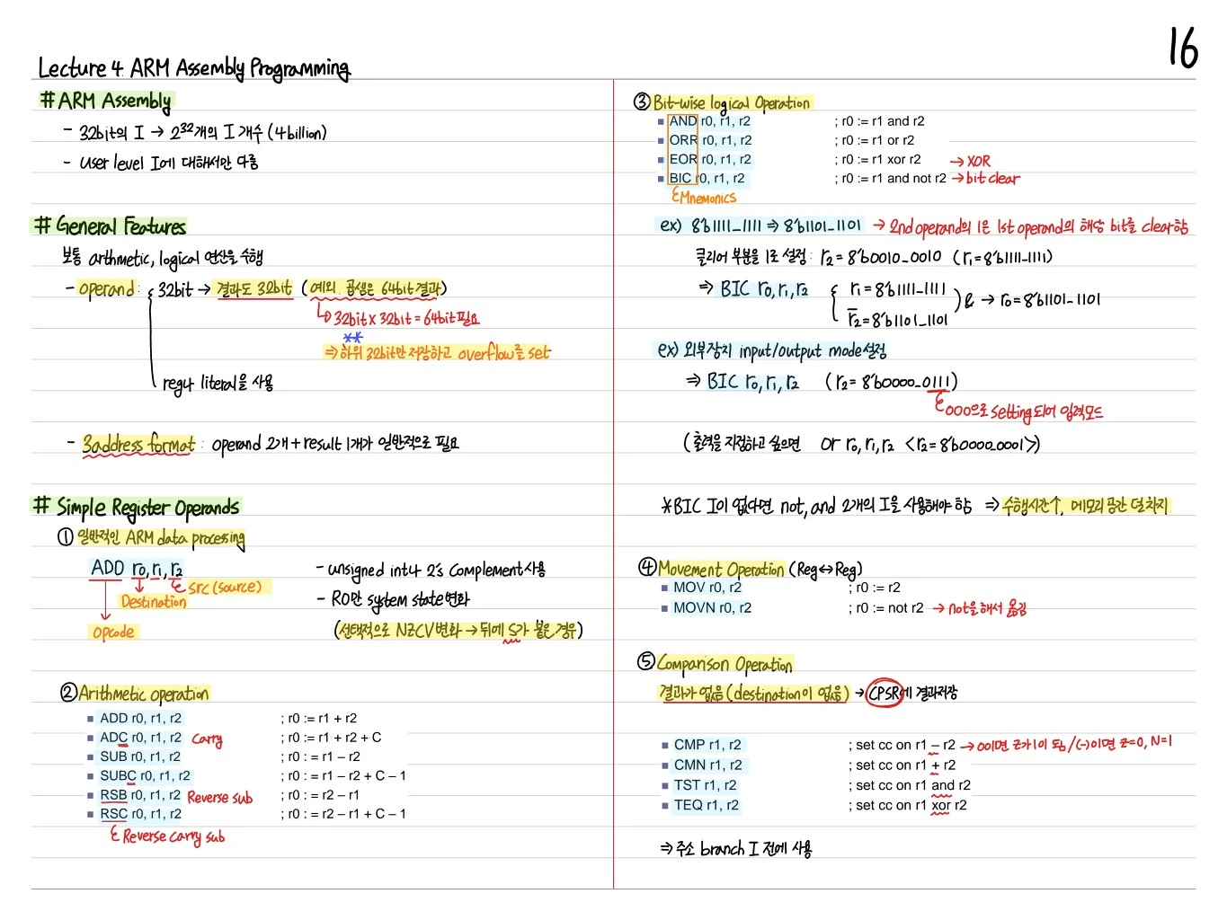
- Arithmetic, Logical Operations: ADD, SUB, AND, ORR, and so on
- ALU operations are register-to-register, with up to 3 operands
Suffixed Format
The form is <instruction>{S}{cond}. S updates the flags, and cond makes the execution conditional.
Example: ADDEQS r0, r1, r2 → executes only when the EQ condition is true, and updates the flags
Simple Register Operands
- ADD r0, r1, r2:
r0 = r1 + r2 - 3-operand or 2-operand form
Arithmetic Operation
- ADD, SUB, RSB (reverse subtract), ADC (add with carry), SBC, RSC
- Why RSB is needed: with immediates, ARM finds both
r0 = r1 - r2andr0 = r2 - r1useful
Bitwise Logical Operation
- AND, ORR, EOR (XOR), BIC (bit clear = AND NOT)
- Example:
BIC r0, r1, #0xFF→ clears the low 8 bits of r1 to 0
Bit Shift Operation
- MOV, MVN (move NOT); can include a shift
Comparison Operation (No destination)
- CMP (compare = SUB, flags only), CMN (compare negative = ADD, flags only)
- TST (test = AND, flags only), TEQ (test equal = EOR, flags only)
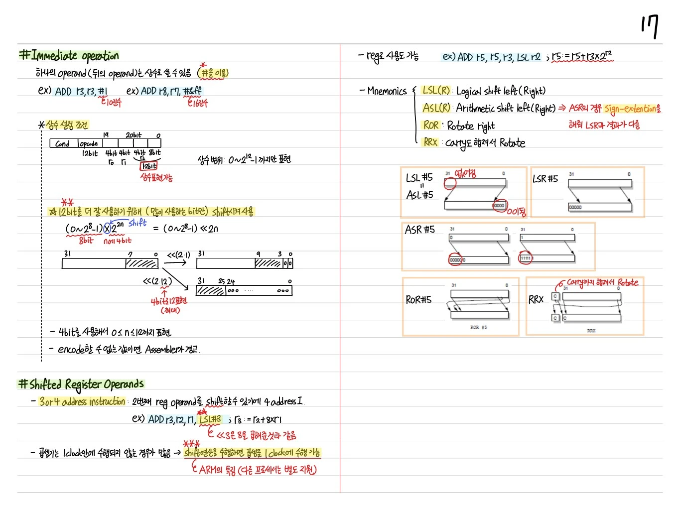
Immediate Operation
One operand (the last one) can be a constant (using #).
Examples: ADD r3, r3, #1, ADD r8, r7, #&ff
Rules for Constants
ARM instructions are a fixed 32 bits, so the immediate gets 12 bits of space. Cond | opcode | 12bit(rn) | 4bit(r1) | 4bit | 4bit 12bit.
- Constant range: only can be represented directly
- To make better use of the 12 bits (only the commonly used bits), the value is shifted
- — 8 bits × a 4-bit shift
- The 4 bits represent
- If a value cannot be encoded, the assembler warns
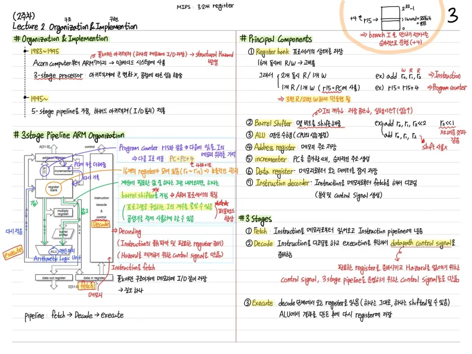
Shifted Register Operands
3- or 4-address instructions: the second register operand can be shifted, which makes it a 4-address instruction.
Example: ADD r3, r2, r1, LSL #3 → r3 = r2 + 8*r1
<<3is the same as multiplying by 8- A multiplier often cannot finish within 1 clock → using a shift, the multiplication can also finish in 1 clock (a feature of ARM; other processors need separate resources)
A register can also be used. Example: ADD r5, r5, r3, LSL r2 → r5 = r5 + r3 * 2^r2
Shift Mnemonics
- LSL(R): Logical shift left (Right)
- ASL(R): Arithmetic shift left (Right) → ASR performs sign extension, so its result differs from LSR
- ROR: Rotate right
- RRX: Rotate including the carry
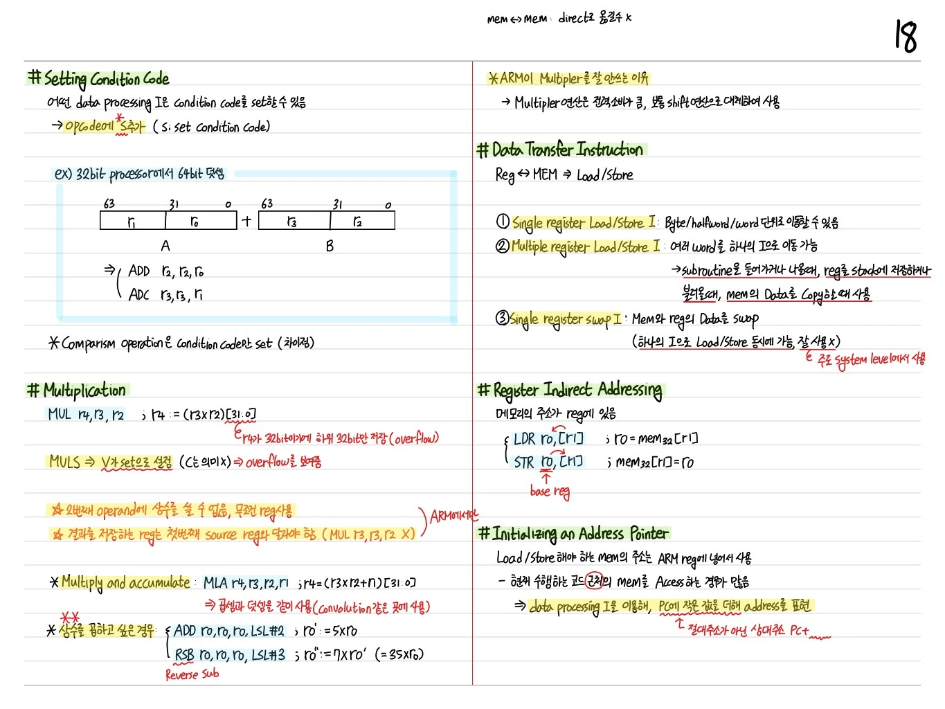
Setting Condition Code
When a condition code suffix is used on a data processing instruction:
- With the S suffix, the condition code result is written to the CPSR
Multiplication
- MUL r0, r1, r2 →
r0 = (r1 * r2)[31:0](low 32 bits only) - MLA r0, r1, r2, r3 →
r0 = (r1 * r2 + r3)[31:0](multiply accumulate) - Multiply and accumulate: MLA r0, r1, r2, r3; MLAS (updates the condition codes)
Data-Transfer Instruction (Load/Store)
Loads/stores registers to and from memory.
- Single register load/store (LDR, STR): byte/halfword/word
- Multiple register load/store (LDM, STM): block transfer
Register Indirect Addressing
Example: LDR r0, [r1] → r0 = mem[r1], STR r0, [r1] → mem[r1] = r0
Initializing an Address Pointer
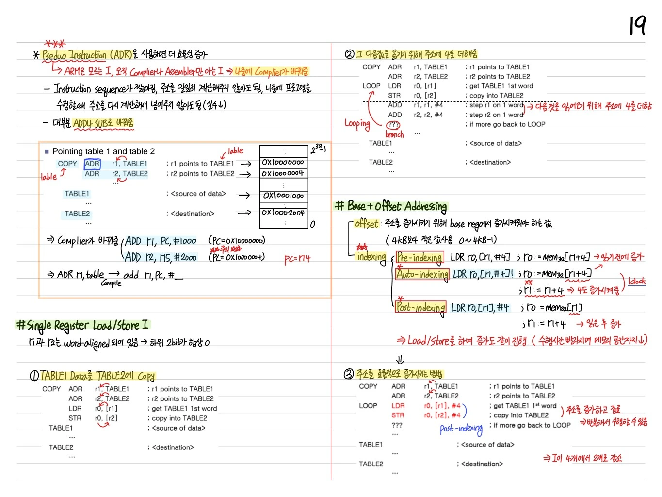
Load from: Load from label; relative to the current PC.
Pointing label 1 and label 2
An example of setting a pointer to labeled data in memory.
Single Register Load/Store Instructions
Understanding the structure through examples of base with offset and pre/post-indexed auto-increment.
Base + Offset Addressing
- Pre-indexed addressing:
LDR r1, [r0, #4]→r1 = mem[r0 + 4], r0 unchanged - Pre-indexed with writeback:
LDR r1, [r0, #4]!→r1 = mem[r0 + 4],r0 = r0 + 4 - Post-indexed:
LDR r1, [r0], #4→r1 = mem[r0],r0 = r0 + 4
Multiple Register Data Transfer
Loads/stores several registers at once.
- LDM (Load Multiple):
LDMIA r0!, {r1-r3}→r1 = mem[r0],r2 = mem[r0+4],r3 = mem[r0+8],r0 = r0 + 12 - STM (Store Multiple): Stores the same way
Addressing Mode
- IA (Increment After), IB (Increment Before), DA (Decrement After), DB (Decrement Before)
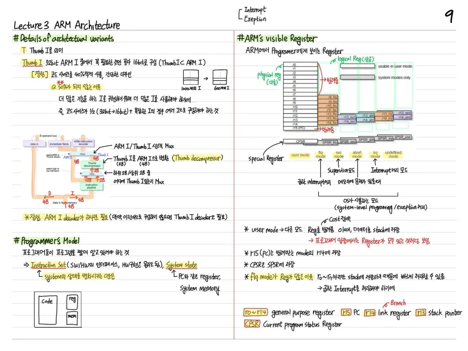
- When used for stacks: FD (Full Descending), FA, ED, EA
Stack Addressing
- Full stack (F): SP points to the last stored value
- Descending stack (D): The stack grows toward lower addresses
ARM uses the standard Full Descending (FD) stack.
Block Copy Addressing
Combining LDMIA/STMIA copies a block of memory efficiently.
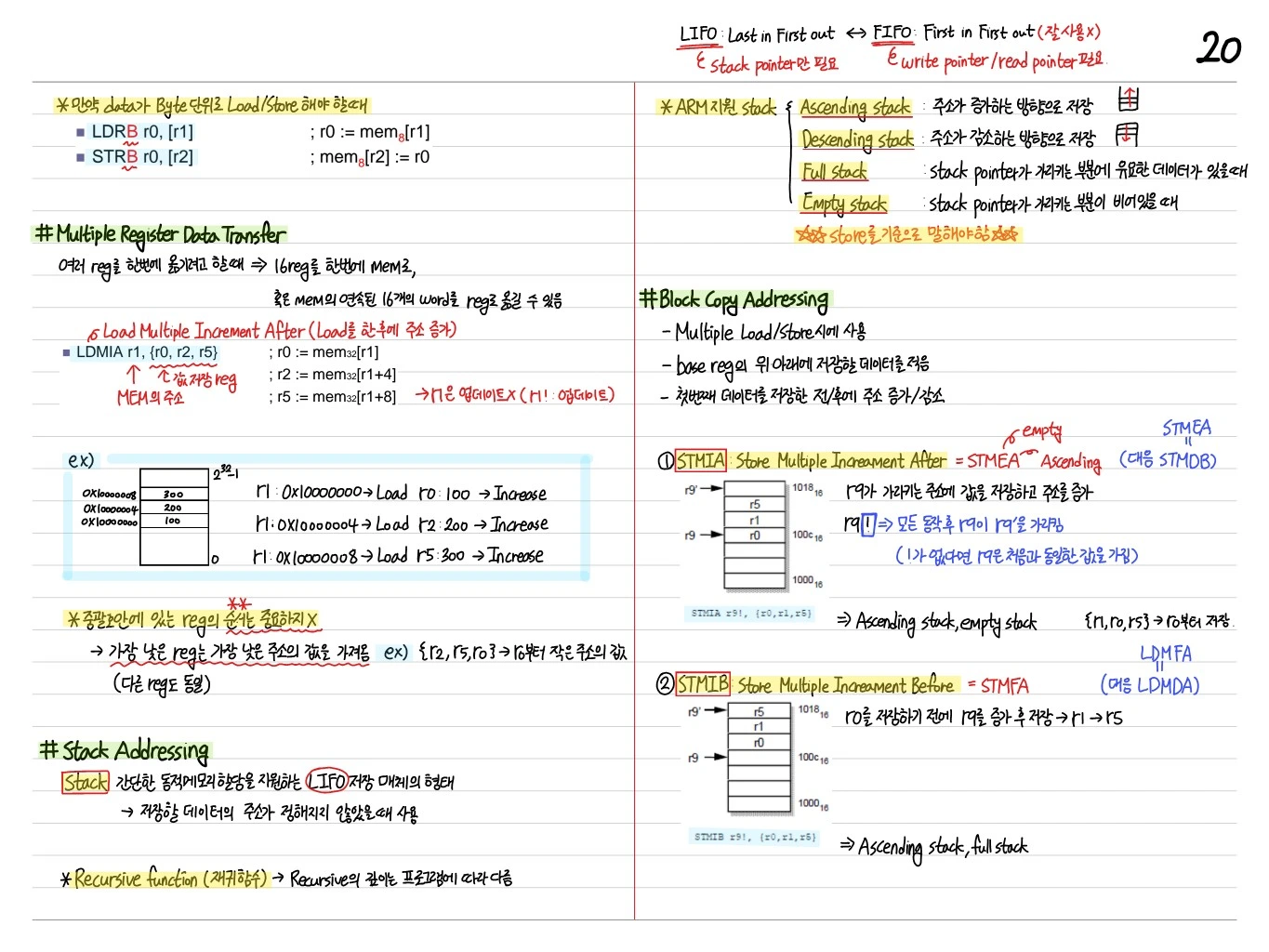
Block Copy Addressing Usage
- LDMIA r8!, {r0-r3}: Load Multiple Increment After (loads 4 registers, updates r8)
- STMIA r9!, {r0-r3}: Store Multiple Increment After
- → The core of a block copy loop
Similarly:
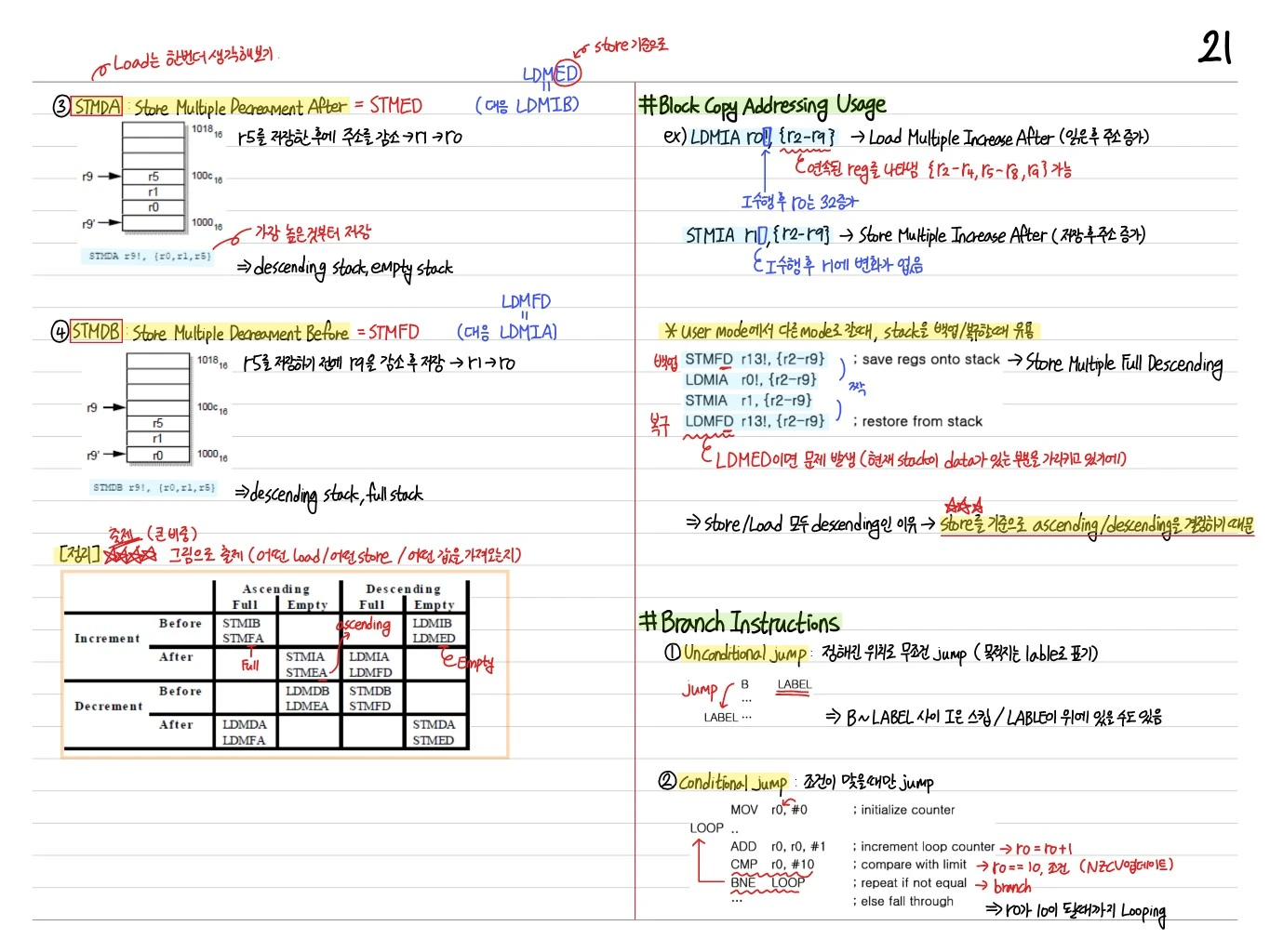
- Full descending stack (STMFD/LDMFD): Stack push/pop
- Descending stack, full-empty check
Branch Instruction
- Unconditional jump:
B label,BL label - Conditional jump:
BEQ label,BNE label, and so on
PC-relative addressing with a 24-bit offset → jumps within a ±32MB range.
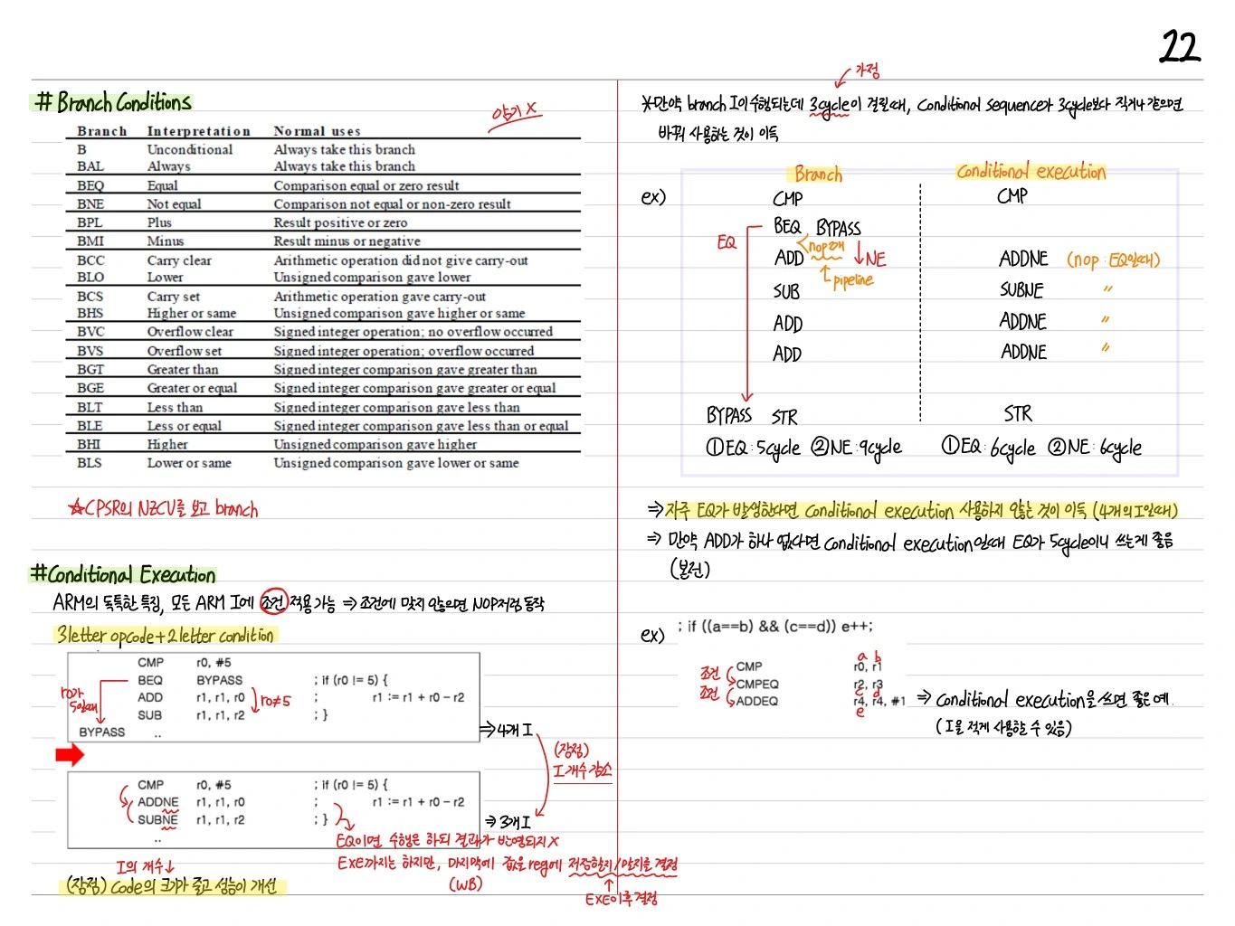
Branch Condition
| Branch | Interpretation | Flag state |
|---|---|---|
| BEQ | Equal | Z=1 |
| BNE | Not equal | Z=0 |
| BCS/BHS | Carry set/unsigned high or same | C=1 |
| BCC/BLO | Carry clear/unsigned low | C=0 |
| BMI | Minus | N=1 |
| BPL | Plus | N=0 |
| BVS | Overflow set | V=1 |
| BVC | Overflow clear | V=0 |
| BHI | Higher (unsigned) | C=1 AND Z=0 |
| BLS | Lower or same (unsigned) | C=0 OR Z=1 |
| BGE | Greater or equal (signed) | N=V |
| BLT | Less than (signed) | N≠V |
| BGT | Greater than (signed) | Z=0 AND N=V |
| BLE | Less or equal (signed) | Z=1 OR N≠V |
Conditional Execution
Conditional execution is used where you would normally branch.
if (r1 > r0) { r0 = r0 - 2; } else { r0 = r0 + 2; }Using a normal branch:
CMP r0, r1
BGT ELSE
SUB r0, r0, #2
B END
ELSE:
ADD r0, r0, #2
END:
Using conditional execution:
CMP r0, r1
SUBLE r0, r0, #2   ; executes if the condition is LE
ADDGT r0, r0, #2   ; executes if the condition is GT
→ Removing the branch keeps the pipeline efficient. A powerful feature unique to ARM.
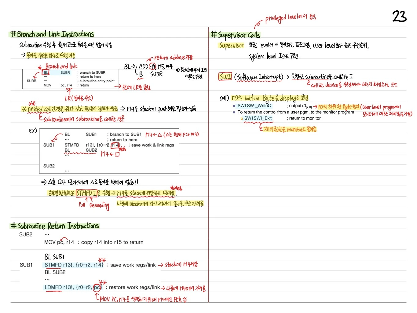
Branch and Link Instructions
Often used to return to the original code after running a subroutine.
- BL SUBR: Branch to SUBR with Link
r14 = r15 - 4(saves the return address) → restores LR into the PC
- B SUBR: Branch only (no link)
Nested Calls
The approach above breaks down → r14 needs to be pushed onto the stack (when a subroutine calls another subroutine).
Example:
BL SUB1         ; branch to SUB1, r14 ← △ (△ is the current PC + #4)
                ; return to here
SUB1 STMFD r13!, {r0-r2, r14}  ; save work & link regs
     BL SUB2    ; r14 ← □
     ...
SUB2 ...
→ △ gets overwritten, so there is no way to return to △!
The fix is to execute an STMFD instruction → save r14 to the stack before it is overwritten, using the Full Descending scheme. Later, pop it back off the stack to get the return address.
Subroutine Return Instructions
SUB2 ...
     MOV pc, r14    ; copy r14 into r15 to return

BL SUB1
SUB1 STMFD r13!, {r0-r2, r14}   ; save work regs/link → save r14 on the stack
     BL SUB2
     ...
     LDMFD r13!, {r0-r2, pc}    ; restore work regs/link → later restored from the saved r14
     ; PC is used instead of r14 to skip MOV PC, r14
Supervisor Calls (Running at the Privileged Level)
Supervisor: A program that runs at a privileged level, with higher priority than the user level, implemented with system-level instructions.
SWI (Software Interrupt)
An instruction that calls a special subroutine (code that checks whether the called device should be serviced).
Example: send the bottom byte of r0 to the display:
SWI SWI_WriteC    ; output r0[7:0] → outputs the lowest byte of r0 (the user-level program
                  ; takes control of the monitor)
SWI SWI_Exit— return to monitor (hands control back to the monitor)