Chapter 5: Cortex-M3 Overview
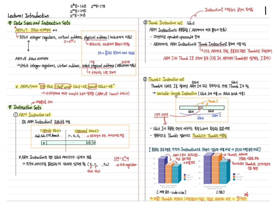
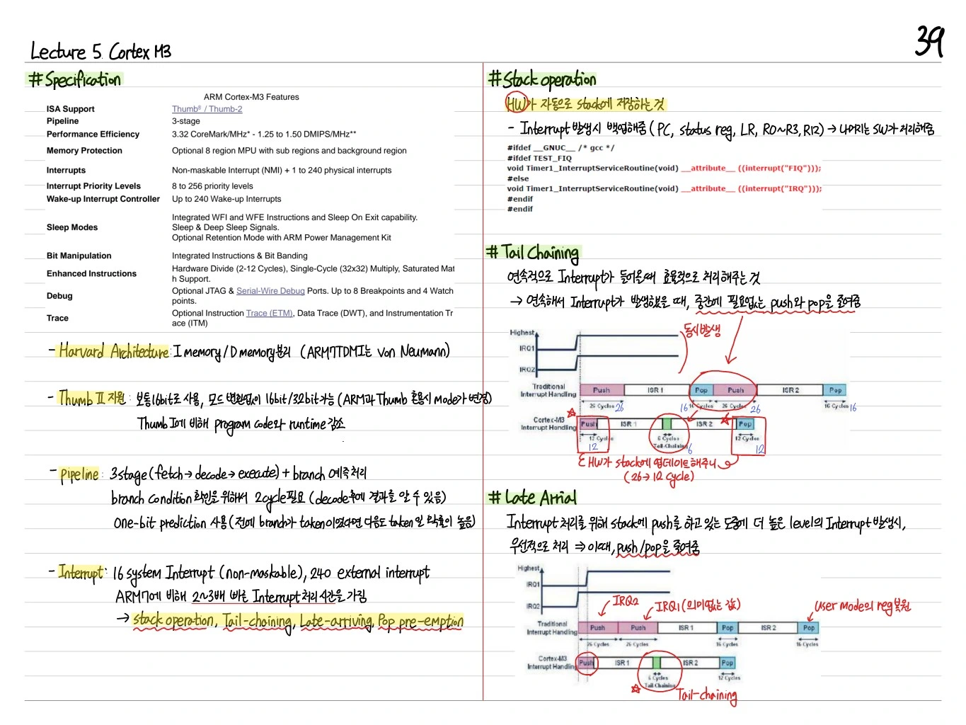
The ARM Cortex-M3 is a processor based on the ARMv7-M architecture for embedded microcontrollers. Its features include Thumb-2 instruction support, a 3-stage pipeline, the NVIC (Nested Vectored Interrupt Controller), and memory-mapped bit-banding.
Specification
| Item | Value |
|---|---|
| ISA Support | ARMv7-M (Thumb-2) |
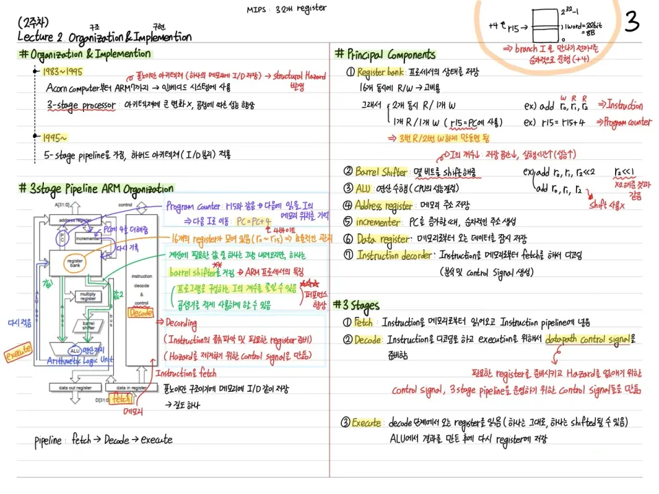
| Pipeline | 3 stages (Fetch-Decode-Execute) |
| Performance Efficiency | 1.25 DMIPS/MHz |
| Memory Protection | Optional MPU |
| Interrupt Priority Levels | 3~256 |
| Instruction/Data Bus | Harvard architecture (separate I-bus, D-bus) |
| Sleep Modes | Integrated WFI, WFE, sleep-on-exit |
| Debug | Serial Wire / JTAG |
Harvard Modified Memory Architecture
Harvard: instructions and data are accessed over separate buses, allowing parallel access and more bandwidth.
Pipeline (3-Stage)
The Cortex-M3 uses a 3-stage pipeline:
- Fetch: fetches the instruction from memory
- Decode: interprets the instruction, reads registers, and performs branch prediction
- Execute: ALU operations, memory access, writeback
A branch misprediction flushes the pipeline → a stall occurs. Late arrival: when the next instruction waits for the branch result.
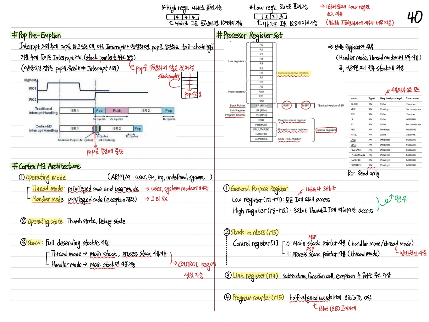
Cortex-M3 Architecture
- Operating Mode: Thread mode, Handler mode
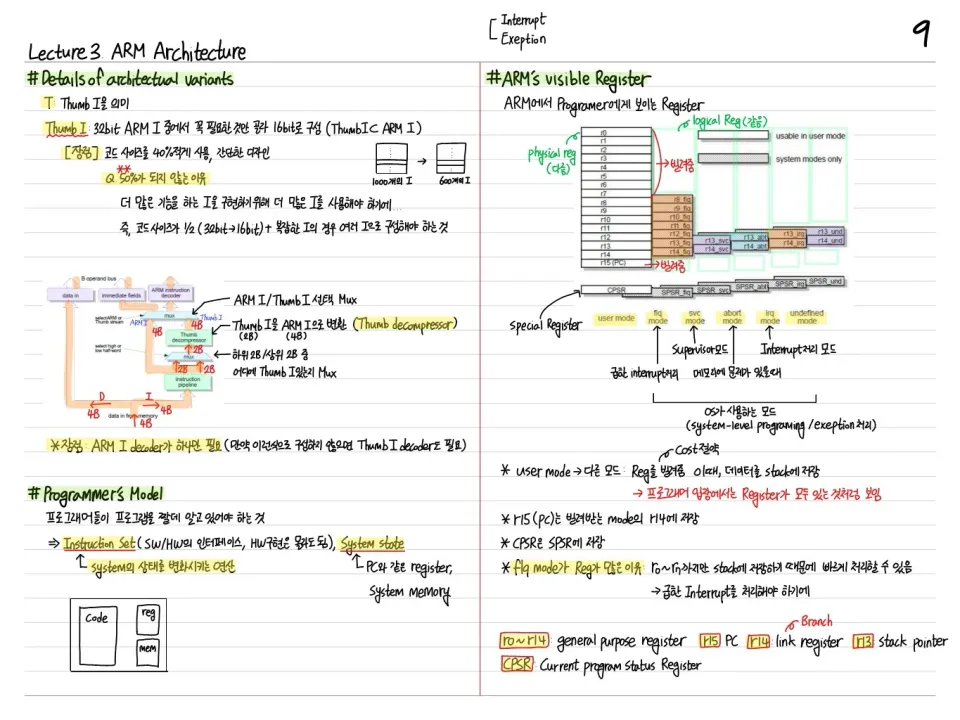
- Processor Register Set: R0~R12 (general), R13 (SP), R14 (LR), R15 (PC), xPSR
- Banked stacks: MSP (Main Stack Pointer) for the OS/exceptions, PSP (Process Stack Pointer) for user threads
General Purpose Registers (R0~R12)
- Low registers (R0~R7): used directly by 16-bit Thumb instructions
- High registers (R8~R12): mostly used directly only by 32-bit Thumb-2 instructions
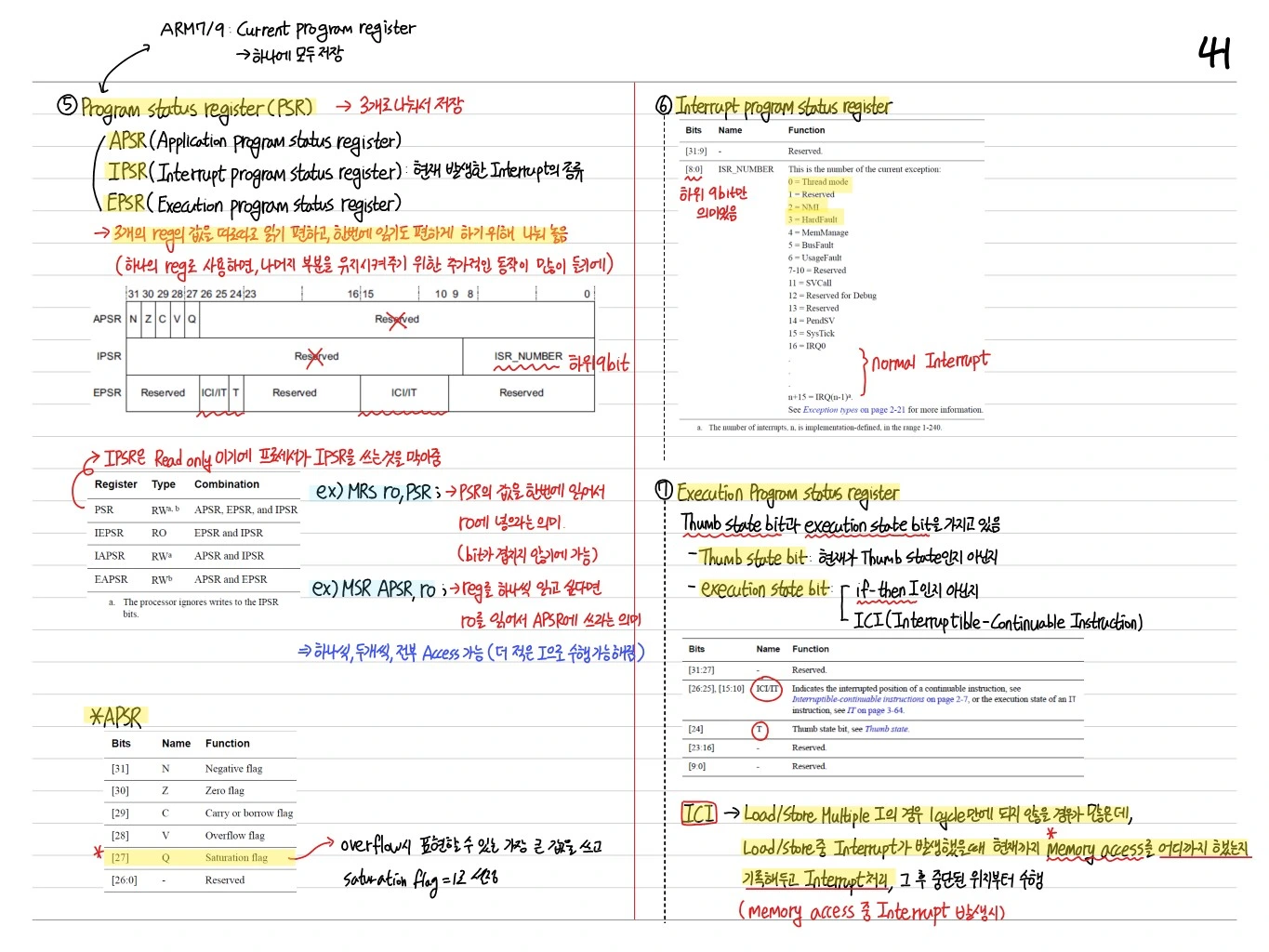
Program Status Register (xPSR)
ARMv7-M accesses xPSR as three parts:
- APSR: N, Z, C, V, Q flags
- IPSR: the number of the exception currently executing
- EPSR: Thumb state bit, IT block state, ICI bits
APSR Flags
- N(bit 31): Negative, Z(bit 30): Zero, C(bit 29): Carry, V(bit 28): Overflow, Q(bit 27): Sticky saturation
IPSR
- bits[8:0]: the current exception number. 0 in Thread mode.
EPSR
- Thumb bit: Cortex-M supports only Thumb mode → always 1
- IT bit: the conditional execution state of an IT (If-Then) block
Special Purpose Registers
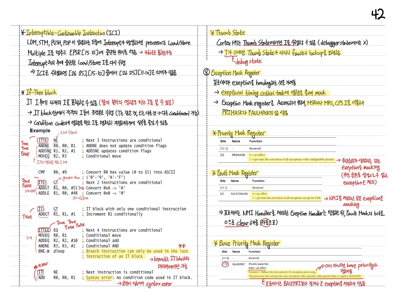
PRIMASK
A 1-bit flag. When 1, configurable exceptions are masked (NMI and HardFault are exempt).
FAULTMASK
A 1-bit flag. When 1, all exceptions except NMI are masked.
BASEPRI
An 8-bit priority. Masks interrupts with lower priority than this value.
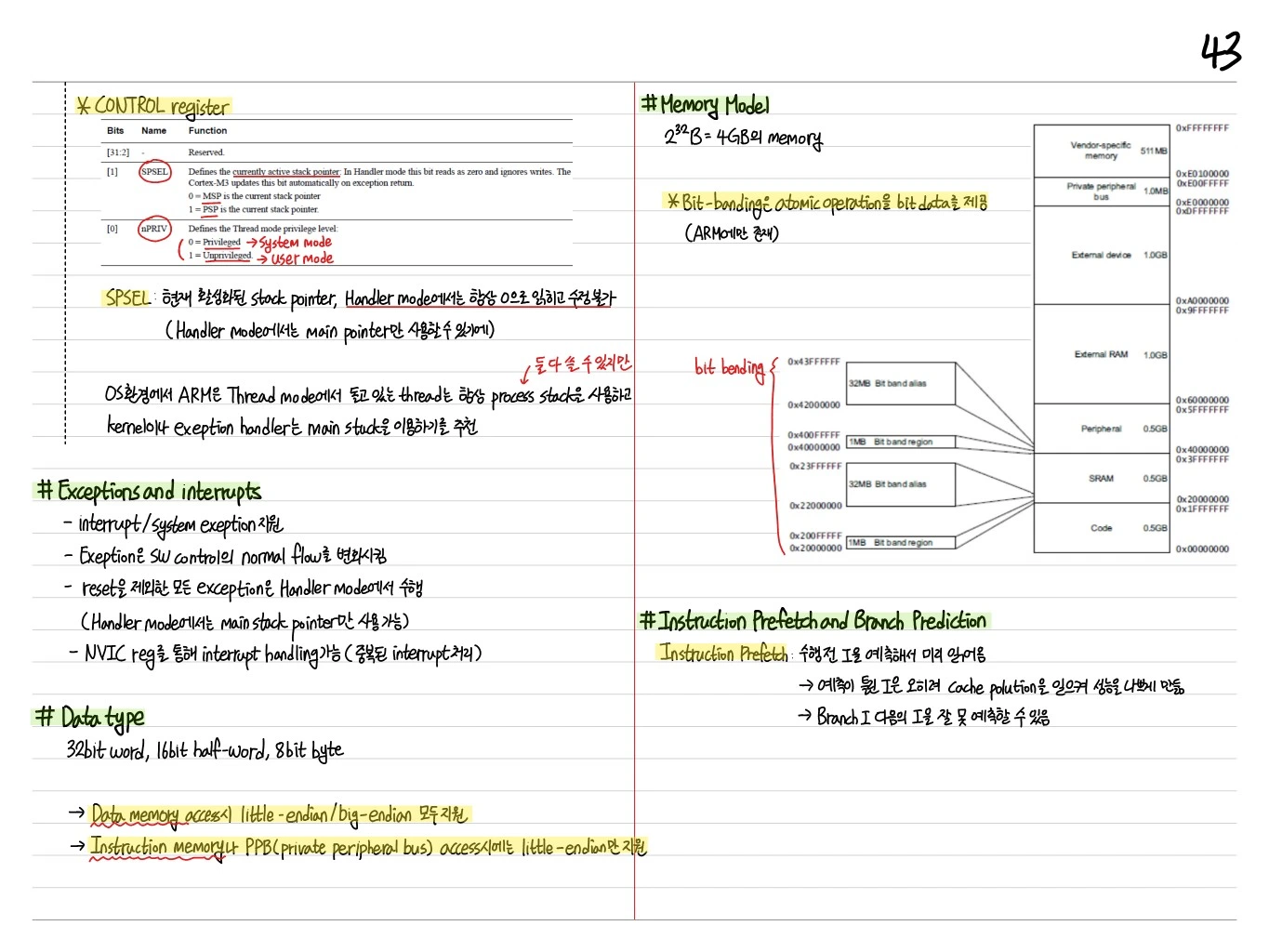
CONTROL
- SPSEL (bit 0): active stack pointer (0=MSP, 1=PSP)
- nPRIV (bit 1): privilege level (0=privileged, 1=unprivileged)
IT (If-Then) Block
Conditional execution in Thumb-2. Up to four conditional instructions can follow an IT instruction:
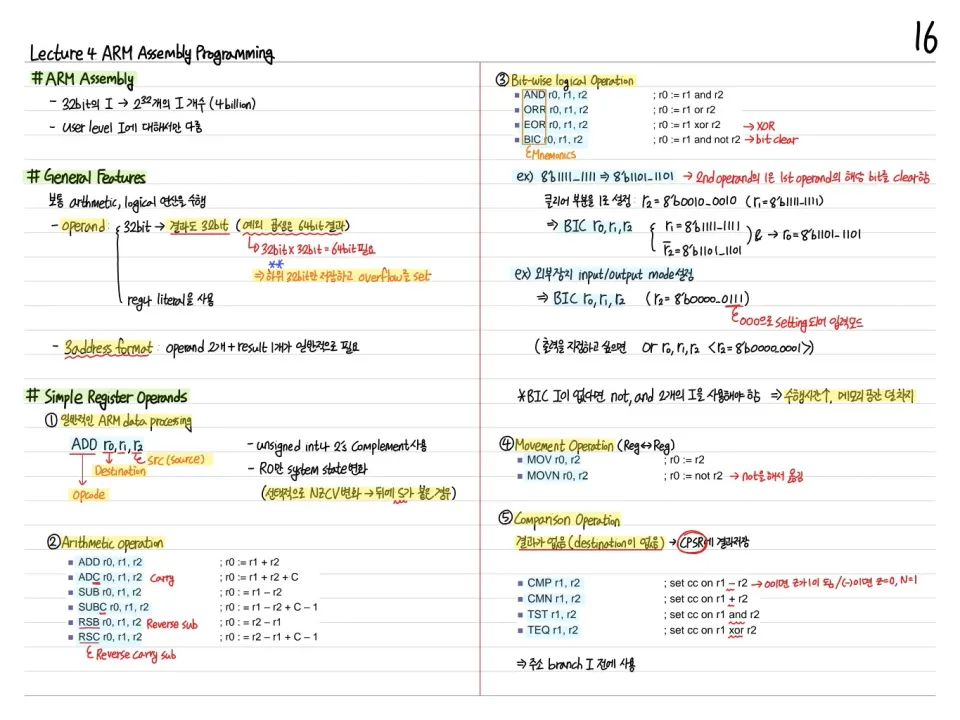
CMP r0, r1
ITTE  EQ
MOVEQ r2, r3
ADDEQ r4, r4, #1
MOVNE r5, r6
→ Conditional execution without a branch → better pipeline efficiency.
CONTROL Register in Detail
| Bits | Name | Function |
|---|---|---|
| [31:2] | Reserved | - |
| [1] | SPSEL | Active stack pointer (0=MSP, 1=PSP). Handler mode: always 0 |
| [0] | nPRIV | Thread mode privilege (0=Privileged, 1=Unprivileged) |
- SPSEL: the currently active stack pointer. In Handler mode it always reads as 0 and cannot be modified
- In an OS environment, ARM recommends that threads in Thread mode always use the process stack, while the kernel and exception handlers use the main stack
Exceptions and Interrupts
- Supports interrupts and system exceptions
- An exception changes the normal flow of software control
- All exceptions except Reset run in Handler mode
- Interrupts are handled through the NVIC registers (handling nested interrupts)
Data Types
- 32-bit word, 16-bit half-word, 8-bit byte
- Data memory access: supports both little-endian and big-endian
- Instruction memory, PPB access: little-endian only
Memory Model
B = 4 GB of memory.
0xFFFFFFFF  Vendor-specific (511 MB)
0xE0100000
0xE00FFFFF  Private peripheral bus (1.0 MB)
0xE0000000
0xDFFFFFFF  External device (1.0 GB)
0xA0000000
0x9FFFFFFF  External RAM (1.0 GB)
0x60000000
0x5FFFFFFF  Peripheral (0.5 GB)  — bit-banding region
0x40000000
0x3FFFFFFF  SRAM (0.5 GB)  — bit-banding region
0x20000000
0x1FFFFFFF  Code (0.5 GB)
0x00000000
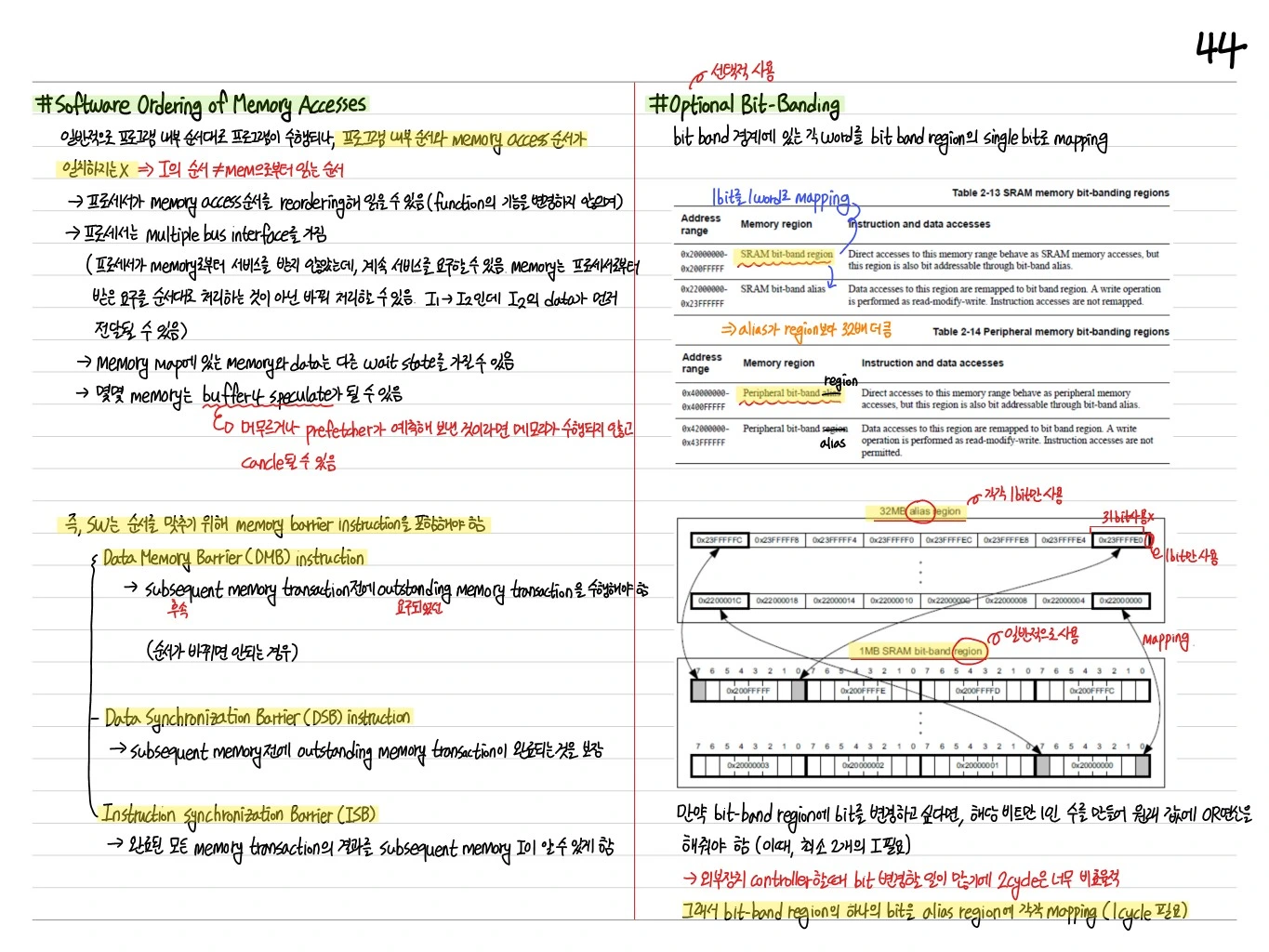
Bit-Banding
A Cortex-M3 feature: atomic operations on bit data (unique to ARM).
- In the 0.5GB peripheral and 0.5GB SRAM regions, a 1MB bit-band region → a 32MB bit-band alias
- One word (32-bit) in the alias maps to one bit in the bit-band region
- Reading or writing an alias address reads or modifies only that bit, atomically
Instruction Prefetch and Branch Prediction
Instruction prefetch: predicts instructions before they execute and reads them ahead of time.
- A mispredicted instruction causes cache pollution and hurts performance
- The instruction after a branch can be mispredicted
Software Ordering of Memory Access
- DMB (Data Memory Barrier): later accesses happen only after earlier memory accesses complete
- DSB (Data Synchronization Barrier): DMB + guarantees completion of instructions
- ISB (Instruction Synchronization Barrier): pipeline flush
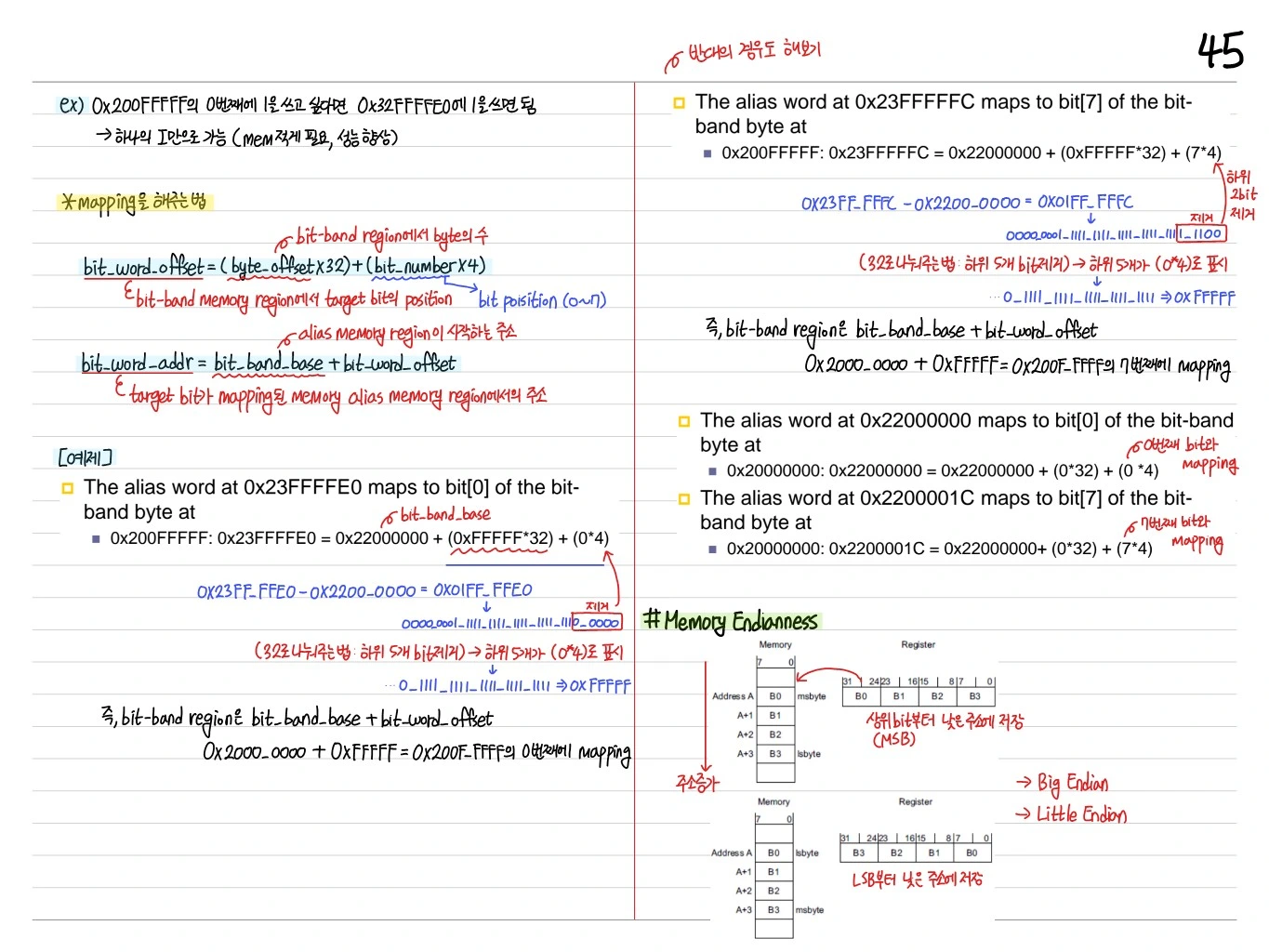
Bit-Banding Address Translation
bit_word_offset = (byte_offset x 32) + (bit_number x 4)
bit_word_addr = bit_band_base + bit_word_offset
Example: SRAM bit-band region 0x20000000 → alias 0x22000000
- 0x20000000 bit 0 → 0x22000000
- 0x20000000 bit 1 → 0x22000004
- 0x20000000 bit 2 → 0x22000008
Memory Endianness
- Big endian or little endian can be selected
- Cortex-M3 code fetches are always little-endian
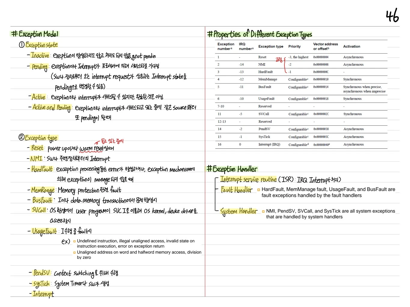
Exception Model
The Cortex-M3 exception scheme: Reset, NMI, HardFault, MemManage, BusFault, UsageFault, SVCall, DebugMonitor, PendSV, SysTick, IRQ[0..239].
Exception Types (in priority order)
- Reset: highest (fixed)
- NMI: second (fixed)
- HardFault: fault escalation
- Configurable: MemManage, BusFault, UsageFault, SVCall, DebugMonitor, PendSV, SysTick, IRQ
- IRQ: external peripherals
Exception Handlers
- ISR (Interrupt service routine): IRQ handler
- Fault handler: HardFault, MemManage, UsageFault, BusFault
- System handler: NMI, PendSV, SVCall, SysTick
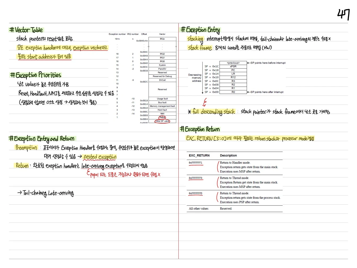
Vector Table
Contains the reset value of the stack pointer and the start addresses of all exception handlers.
| Exception number | IRQ number | Offset | Vector |
|---|---|---|---|
| 16+n | n | 0x0040+4n | IRQn |
| 15 | -1 | 0x003C | SysTick |
| 14 | -2 | 0x0038 | PendSV |
| 11 | -5 | 0x002C | SVCall |
| 6 | -10 | 0x0018 | Usage fault |
| 5 | -11 | 0x0014 | Bus fault |
| 4 | -12 | 0x0010 | Memory management fault |
| 3 | -13 | 0x000C | Hard fault |
| 2 | -14 | 0x0008 | NMI |
| 1 | - | 0x0004 | Reset |
| 0 | - | 0x0000 | Initial SP value |
Exception Priorities
A lower value means a higher priority.
- Priorities can be set for all exceptions except Reset, HardFault, and NMI
- If not set, the priority is 0 → it is better to set it
Exception Entry and Return
Preemption
If a higher-priority exception occurs while the processor is running an exception handler, it preempts → a nested exception.
Return
A completed exception handler does not run a late-arriving exception. It can during the pop, but not once the pop is complete.
→ Tail-chaining and late-arriving optimizations.
Exception Entry: Stacking
- Stacking: on an interrupt, state is backed up to the stack; this is skipped for tail-chained or late-arriving exceptions
- Stack frame: 8 words are backed up automatically (in HW)
SP + 0x1C    <previous>
SP + 0x18    xPSR
SP + 0x14    PC
SP + 0x10    LR
SP + 0x0C    R12
SP + 0x08    R3
SP + 0x04    R2
SP + 0x00    R1, R0
Full descending stack: the stack pointer points to the low end of the stack frame.
Exception Return
The EXC_RETURN[3:0] value determines the return stack and processor mode.
| EXC_RETURN | Description |
|---|---|
| 0xFFFFFFF1 | Return to Handler mode. State from MSP. Execution uses MSP. |
| 0xFFFFFFF9 | Return to Thread mode. State from MSP. Execution uses MSP. |
| 0xFFFFFFFD | Return to Thread mode. State from PSP. Execution uses PSP. |
Summary
| Element | Description |
|---|---|
| ARMv7-M, Thumb-2 | Mixed 16/32-bit instructions |
| 3-stage pipeline | Fetch-Decode-Execute + branch prediction |
| Harvard arch | Separate I-bus and D-bus |
| MSP / PSP | Separate stack pointers for the OS and threads |
| xPSR = APSR+IPSR+EPSR | Flags, exception number, Thumb/IT state |
| Bit-banding | Atomic bit access via alias address |
| NVIC + Tail-chaining | Low-latency nested interrupts |
| Memory barrier | Multi-master synchronization with DMB/DSB/ISB |
The Cortex-M3 became the standard of the low-power embedded MCU market (STM32, LPC17xx, and others) and was later extended into the Cortex-M4 and M7.