Key points in three lines
- The immediate generator is the selector table from Part 2 turned into seven selectors, one per group of output bits. Across 1 million cases (200,000 random instructions × 5 formats), it matched a per-format bit-concatenation calculation every time.
- A single-cycle datapath runs all of RV32I with a PC, instruction memory, register file (2 reads, 1 write), ALU, and data memory, plus five selectors (ALU inputs A and B, write-back, next pc, immediate format). I traced
lw,bltu, andretthrough this path with real values. - Running 5 compiled programs (1,076,364 instructions) on this model matched QEMU on UART output, the per-instruction pc trace, and final registers. Of the executed instructions, 20.0% were branches and 6.1% were jumps, and 58.5% of branches were taken. This is the basis for the CPI analysis in Part 17.
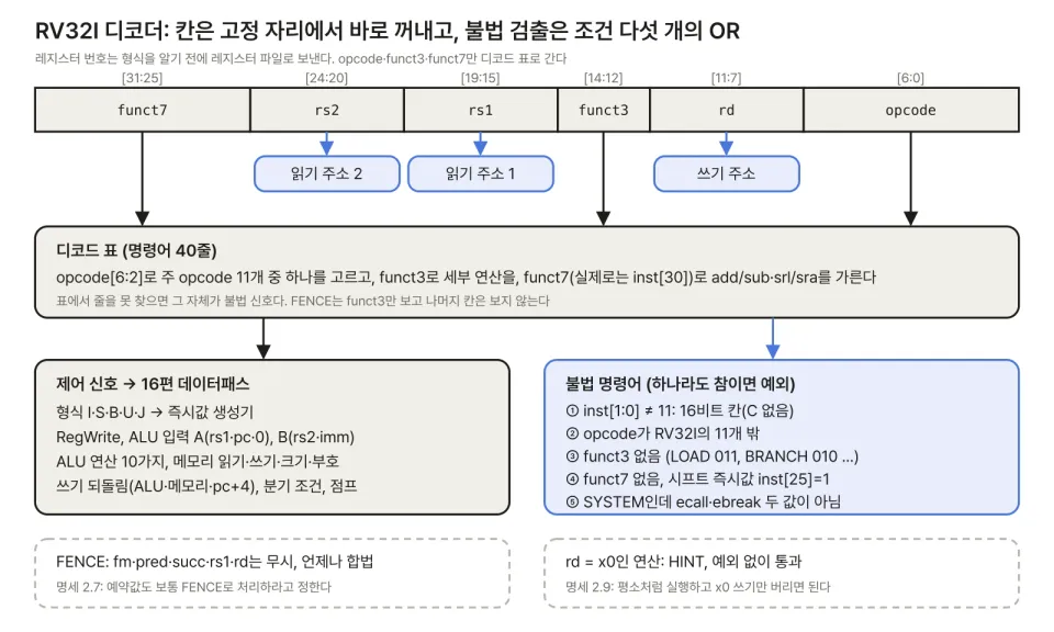
In Part 15, I built a decoder that takes one instruction and outputs register numbers, the format, control signals, and an illegal-instruction flag. This part builds the piece that takes those outputs and actually computes: the datapath. First I turn the immediate layout, which Part 2 only showed as a table, into a circuit, then I assemble the simplest core that finishes one instruction per cycle, a single-cycle datapath. A single-cycle core is slow, but it shows most clearly "what an instruction passes through," and the pipeline in Part 17 is just this picture cut into five pieces.
1. The Immediate Generator: Part 2's Table as a Circuit
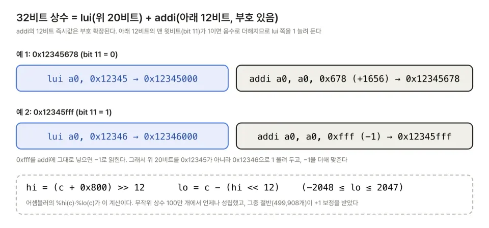
In Part 2, I made a table showing, for each immediate output bit, "which instruction bit it comes from for each format." Grouping bits with the same source gives seven groups of output bits, with one selector per group.
| Output bits | Selection rule | Inputs |
|---|---|---|
| imm[31] | Always inst[31] | 1 |
| imm[30:20] | inst[30:20] for U, otherwise sign | 2 |
| imm[19:12] | inst[19:12] for U and J, otherwise sign | 2 |
| imm[11] | B: inst[7], J: inst[20], U: 0, others: sign | 4 |
| imm[10:5] | 0 for U, otherwise inst[30:25] | 2 |
| imm[4:1] | I and J: inst[24:21], S and B: inst[11:8], U: 0 | 3 |
| imm[0] | I: inst[20], S: inst[7], others: 0 | 3 |
Here "sign" means inst[31] replicated to that width. The only select signals are the five format signals (I, S, B, U, J) from the decoder. The R format has no immediate, so the output does not matter. In the model, I copied this table directly.
def imm_gen(w, fmt):
    s = w >> 31                       # the sign is always inst[31]
    fill = lambda n: ((1 << n) - 1) if s else 0
    I, S, B, U, J = (fmt == f for f in 'ISBUJ')
    i30_20 = bits(w, 30, 20) if U else fill(11)
    i19_12 = bits(w, 19, 12) if (U or J) else fill(8)
    i11 = (bits(w, 7, 7) if B else bits(w, 20, 20) if J
           else 0 if U else s)
    i10_5 = 0 if U else bits(w, 30, 25)
    i4_1 = (bits(w, 24, 21) if (I or J)
            else bits(w, 11, 8) if (S or B) else 0)
    i0 = bits(w, 20, 20) if I else bits(w, 7, 7) if S else 0
    return (s << 31 | i30_20 << 20 | i19_12 << 12
            | i11 << 11 | i10_5 << 5 | i4_1 << 1 | i0)
When moving to RTL, each line becomes one assign. I compared the Part 2 approach (concatenate bits per format, then sign-extend) against this circuit form on 200,000 random instructions with all five formats applied (seed 16). All 1 million cases matched.
Let's check one by hand. bltu a5, a0, +24 is 0x00a7ec63. It is B format, so imm[11]=inst[7]=0, imm[10:5]=inst[30:25]=000000, imm[4:1]=inst[11:8]=1100, imm[0]=0, and the upper bits are filled with the sign inst[31]=0. Put together, it is 1100 followed by a 0, which is 24.
2. Datapath Blocks
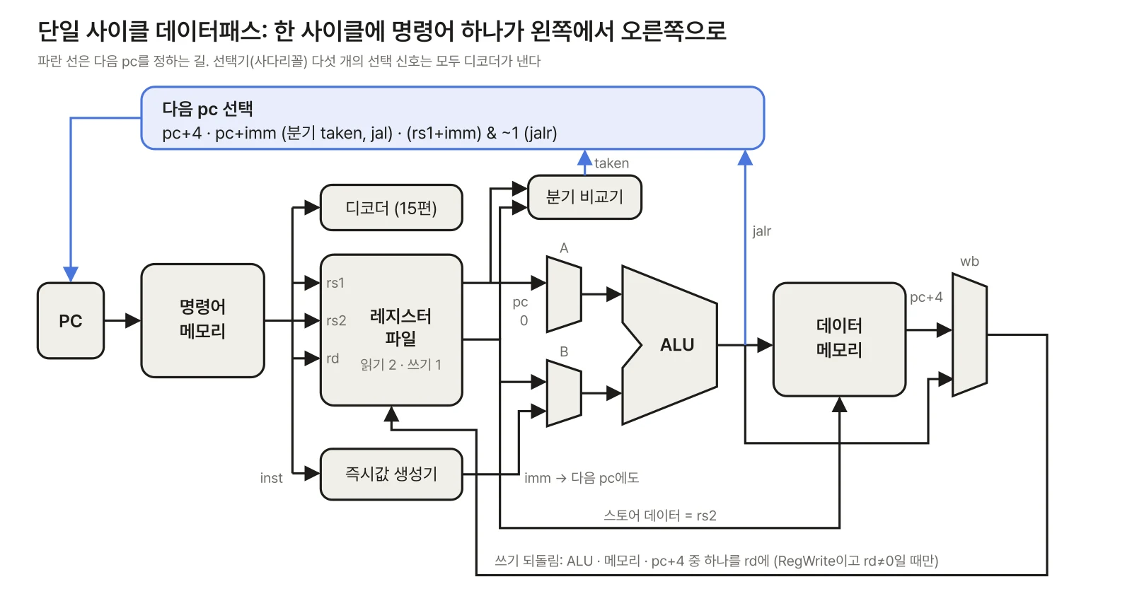
Here is what each block does and how big it is.
| Block | Input → output | Notes |
|---|---|---|
| PC | next pc → pc | One 32-bit register |
| Instruction memory | pc → inst | Read-only, assumed combinational read |
| Register file | rs1, rs2, rd, write value | 2 read ports, 1 write port, x0 is 0 |
| ALU | A, B, op → result | The 10 operations from Part 3 |
| Branch comparator | rs1, rs2, condition → taken | 6 conditions |
| Data memory | address, write value → read value | Byte, halfword, word |
There is a reason to separate the ALU and the branch comparator. A textbook design that decides the beq family with the ALU's subtraction and "is the result zero" is possible (DDCA 7.3). But adding blt, bge, bltu, and bgeu attaches several more flag outputs to the ALU, and the branch target pc+imm needs a separate adder anyway (since the ALU is busy with the comparison). With a separate comparator, the ALU only "produces values," and when Part 18 moves the branch decision into the ID stage, only the comparator has to move.
There are five selectors.
| Selector | Inputs | Select signal |
|---|---|---|
| ALU input A | rs1 · pc · 0 | auipc=pc, lui=0 |
| ALU input B | rs2 · imm | rs2 only for R format and branches |
| Write-back | ALU · memory · pc+4 | loads=memory, jal/jalr=pc+4 |
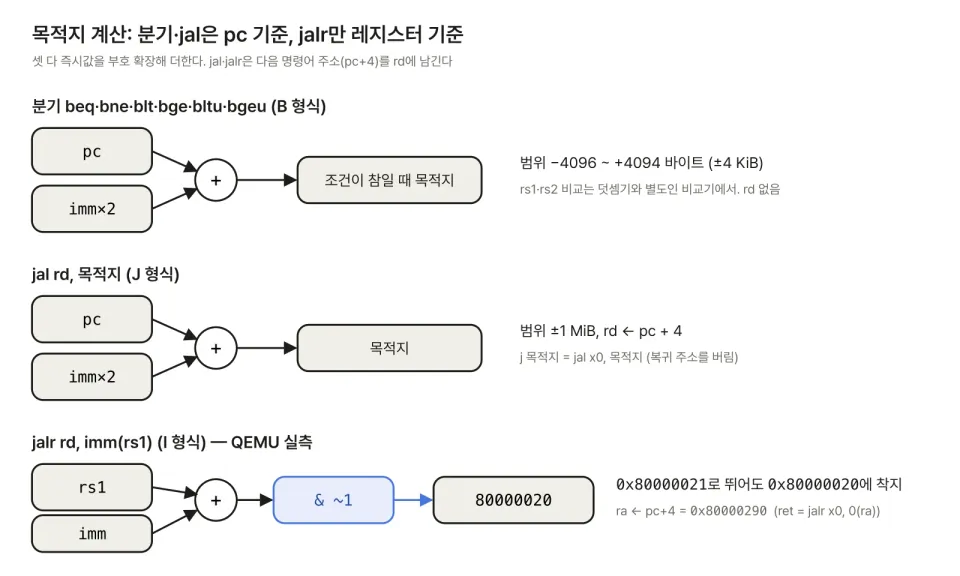
| Next pc | pc+4 · pc+imm · (rs1+imm)&~1 | taken branch/jal / jalr |
| Immediate format | I · S · B · U · J | Inside the circuit from section 1 |
Feeding 0 into ALU input A lets lui be computed as "0 + imm." Another option is to add a selector input just for lui on the write-back side instead of 0. Either way, it adds one input.
3. Widening the Datapath One Format at a Time
If you draw the whole datapath from the start, it is easy to lose track of why each wire is there. Adding instruction types one at a time and growing only the wires you need is easier to follow (the same approach as DDCA 7.3, which starts from lw).
| Order | Instruction | What is added |
|---|---|---|
| 1 | lw |
PC, both memories, register read 1 and write, I immediate, ALU add |
| 2 | sw |
Register read 2, S immediate, memory write |
| 3 | R format | ALU input B selector (rs2/imm), 10 ALU operations, write-back selector |
| 4 | I arithmetic | Nothing (a combination of 1–3) |
| 5 | Branches | Comparator, B immediate, pc+imm adder, next-pc selector |
| 6 | jal |
J immediate, pc+4 on write-back |
| 7 | jalr |
ALU result & ~1 on next pc |
| 8 | lui, auipc |
U immediate, ALU input A selector (rs1/pc/0) |
It is interesting that step 4 is empty. Immediate operations such as addi, slti, and xori mix lw's "rs1 + I immediate" path with the R-format ALU operations, so no new wires are needed. Of the 40 RV32I instructions, only these eight steps actually widen the datapath. Finally, byte selection and sign-extension circuits are attached before and after the data memory for lb, lh, lbu, lhu, sb, and sh.
4. Tracing Instructions by Hand
Running the compiled fib function on the model, I printed the real values for the first lw, bltu, and ret. The code GCC produced is as follows (beginning).
80000020: addi sp,sp,-16
80000024: sw   ra,12(sp)
80000028: sw   s0,8(sp)
8000002c: mv   s0,a0
80000030: li   a5,1
80000034: bltu a5,a0,8000004c
80000038: mv   a0,s0
8000003c: lw   ra,12(sp)
80000040: lw   s0,8(sp)
80000044: addi sp,sp,16
80000048: ret
bltu a5, a0, 8000004c (pc=0x80000034). The register file reads a5=1 and a0=20 (0x14). The immediate generator produces 24 in B format (section 1). The branch comparator evaluates the unsigned comparison 1 < 20 as true, and the pc+imm adder produces 0x80000034 + 24 = 0x8000004c. Since the branch is taken, the next-pc selector picks pc+imm. RegWrite=0, no memory access. The ALU computes a useless value this cycle, but it goes nowhere.
lw ra, 12(sp) (pc=0x8000003c). The register file reads sp=0x80003fc0. The immediate generator produces 12 in I format, and with ALU input A=rs1 and B=imm, the addition gives the address 0x80003fcc. The data memory reads the word 0x80000058 at that address, and the write-back selector picks "memory" to write it to ra (x1). The next pc is pc+4. Within this one cycle, instruction memory → register file → ALU → data memory → register file write setup all happen. The longest path, which sets the clock period of a single-cycle core, is usually this lw path.
ret = jalr x0, 0(ra) (pc=0x80000048). The register file reads ra=0x80000058, and the ALU computes ra + 0. The next-pc selector picks "ALU result & ~1" and goes to 0x80000058. Write-back picks pc+4 (0x8000004c), but rd=x0, so it is discarded. The next pc depending on a register value is what makes it different from jal, and it is why a return address stack becomes necessary in Part 18.
Collecting the control signals per instruction gives the following (representative rows from the table in Part 15).
| Instruction | A / B | wb | Next pc |
|---|---|---|---|
add |
rs1 / rs2 | ALU | pc+4 |
addi |
rs1 / imm | ALU | pc+4 |
lw |
rs1 / imm | memory | pc+4 |
sw |
rs1 / imm | none | pc+4 |
bltu |
unused | none | pc+imm if taken |
jal |
unused | pc+4 | pc+imm |
jalr |
rs1 / imm | pc+4 | (rs1+imm)&~1 |
lui |
0 / imm | ALU | pc+4 |
auipc |
pc / imm | ALU | pc+4 |
5. Hands-On: Running Real Programs and Comparing Against QEMU
The model (16/single.py) translates the figure above almost line by line. The core is a single function, step().
def step(self):
    pc, x, mem = self.pc, self.x, self.mem
    d = decode(mem.fetch(pc))                 # decoder from Part 15
    if d.illegal: raise Trap(('illegal', pc, d.w))
    rs1v, rs2v = x[d.rs1], x[d.rs2]            # 2 read ports
    srcA = rs1v if d.a == 'r' else pc if d.a == 'p' else 0
    srcB = rs2v if d.b == 'r' else d.imm
    y = alu(d.op, srcA, srcB)
    taken = d.br is not None and br_taken(d.br, rs1v, rs2v)
    if d.mem == 'r': res = mem.load(y, d.sz, d.us)
    elif d.wb == '4': res = (pc + 4) & 0xFFFFFFFF
    else: res = y
    if taken or d.j == 'jal': nxt = (pc + d.imm) & 0xFFFFFFFF
    elif d.j == 'jalr': nxt = y & ~1
    else: nxt = pc + 4
    if (taken or d.j) and nxt & 3:
        raise Trap(('misaligned', pc, nxt))
    if d.mem == 'w': mem.store(y, d.sz, rs2v)
    if d.rw and d.rd: x[d.rd] = res           # writes to x0 are discarded
    self.pc = nxt
I wrote five test programs in C: recursive quicksort (300 integers), bitwise CRC-32 (2 KiB), recursive Fibonacci fib(20), 16×16 integer matrix multiplication, and a byte-array sieve of Eratosthenes (below 8000). They were compiled with riscv64-elf-gcc 16.2 using -march=rv32i -mabi=ilp32 -O1. RV32I has no multiply, so the * in matrix multiplication becomes a call to libgcc's __mulsi3, which is why I added -lgcc. The startup code and linker script are the shared bare-metal environment used since Part 3.
The model emulates only two devices from the QEMU virt board. Writing a byte to 0x10000000 (UART) appends it to the output, and writing to 0x100000 (the exit device) stops execution. I then captured three things from QEMU 11.1.3 for comparison.
- The UART output string
- The per-instruction pc trace:
-accel tcg,one-insn-per-tb=on -d exec,nochainlogs one line per instruction, and I dropped the 6 reset ROM instructions (around0x1000) and the loop after exit - The 32 registers at start and end:
-d cpu -dfilterdumps only the first instruction and the instant before the exitsw. The model takes its starting registers from QEMU so both start in the same state (QEMU's reset ROM leaves values in a1 and t0)
| Program | Instructions | UART | pc trace | Registers |
|---|---|---|---|---|
| qsort | 38,733 | match | match | match |
| crc32 | 143,474 | match | match | match |
| fib | 339,394 | match | match | match |
| matmul | 420,568 | match | match | match |
| sieve | 134,195 | match | match | match |
A matching pc trace means no branch or jump ever diverged. To rule out QEMU and the model being wrong together, I also computed the answers for crc32, fib, and sieve separately in Python and checked them (zlib.crc32, 6765, 1007 primes).
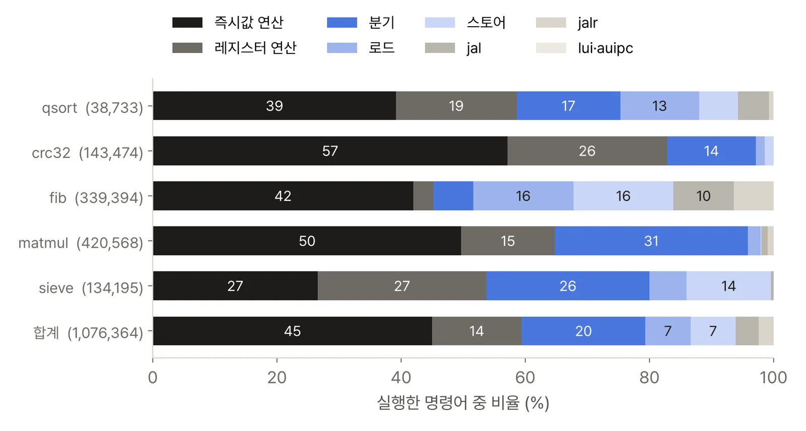
The instruction mix varies quite a bit by program. In total, it was 45.0% immediate arithmetic, 20.0% branches, 14.4% register arithmetic, 7.3% loads, 7.3% stores, 3.7% jal, and 2.4% jalr. There were only 76 lui/auipc instructions (they are used only once to build an address). Two things stand out.
- 31% branches in matmul. With no multiply,
__mulsi3multiplies with a shift-and-add loop. Each inner-loop iteration has two branches. The M extension in Part 19 changes this ratio. - 16% loads and 16% stores, and 16.1% jumps, in fib. Every call saves ra, s0, and s1 to the stack and restores them.
jal(call) andjalr(return) total 54,729.
Of 215,007 branches, 125,866 (58.5%) were taken. On a single-cycle core this costs nothing, because the next pc is chosen in the same cycle. Once Part 17 cuts it into a pipeline, every "taken branch" loses cycles, and the size of that loss comes straight from these numbers.
6. Design Checklist: Immediate Generator and Single-Cycle Datapath
| Item | Rule |
|---|---|
| Immediate sign | inst[31] regardless of format. imm[31] needs no selector |
jalr immediate |
Unlike B and J, it is not doubled (plain I format). After adding, clear the lowest bit of the target |
| Branch target | Relative to the branch instruction's own pc, not pc+4 |
auipc |
Adds the pc of that auipc itself |
| x0 | Reads as 0, writes ignored. Check RegWrite and rd≠0 together |
| Load with rd=x0 | Even if the value is discarded, the memory access and any exception must still happen (spec 2.6) |
| Misaligned target | If the target of a taken branch, jal, or jalr is not a multiple of 4, raise an exception on that jump instruction (without C). Check before writing the register |
| Not-taken branch | No exception even if the target is misaligned |
| Misaligned load/store | The spec leaves it to the EEI. Handle it in hardware or raise an exception (the model just handles it) |
| Next-pc selector | Three inputs: pc+4, pc+imm, (rs1+imm)&~1. Adding traps adds one more, mtvec (Part 25) |
The alignment rows are compared directly against QEMU in Part 18. Spec section 2.6 leaves misaligned loads and stores to the execution environment (EEI). Small cores usually raise an exception and let software handle it.
Summary
- The immediate generator is a set of selectors for seven groups of output bits. The only select signals are the five formats, and it matched the direct calculation in 1 million cases.
- A single-cycle datapath executes all of RV32I with a PC, instruction and data memories, a register file (2R1W), an ALU, a branch comparator, and five selectors. The instruction types that widen the datapath take eight steps, from
lwtolui/auipc. - Running 5 compiled programs, 1,076,364 instructions, on the model matched QEMU on UART, pc trace, and final registers.
- Of the executed instructions, 20.0% were branches (58.5% of them taken) and 6.1% were jumps. In a pipeline, these ratios determine the CPI.
Next post: Part 17 cuts this datapath into five stages: IF, ID, EX, MEM, and WB. Using a cycle-level model, I check what goes into the pipeline registers, the conditions for resolving data hazards with EX/MEM and MEM/WB forwarding and why rd≠x0 must be part of them, load-use stalls, and same-cycle write-then-read in the register file. With the same five programs, I also measure how the CPI changes with forwarding on and off.
References
- The RISC-V Instruction Set Manual, Volume I: Unprivileged Architecture, Version 20240411. 2.3 immediate encoding, 2.4 integer operations (
lui,auipc), 2.5 control transfer (branches,jal,jalr, alignment exceptions), 2.6 loads and stores (loads with rd=x0, alignment). https://github.com/riscv/riscv-isa-manual - D. Harris, S. Harris, Digital Design and Computer Architecture: RISC-V Edition, 2021. 7.3 single-cycle processor (widening the datapath starting from
lw, immediate extension) - D. Patterson, J. Hennessy, Computer Organization and Design: RISC-V Edition, 2nd ed., 2020. 4.3 building a datapath, 4.4 a simple implementation scheme
- QEMU
virtboard and logging options (-d exec,cpu,-dfilter,one-insn-per-tb). https://www.qemu.org/docs/master/system/riscv/virt.html