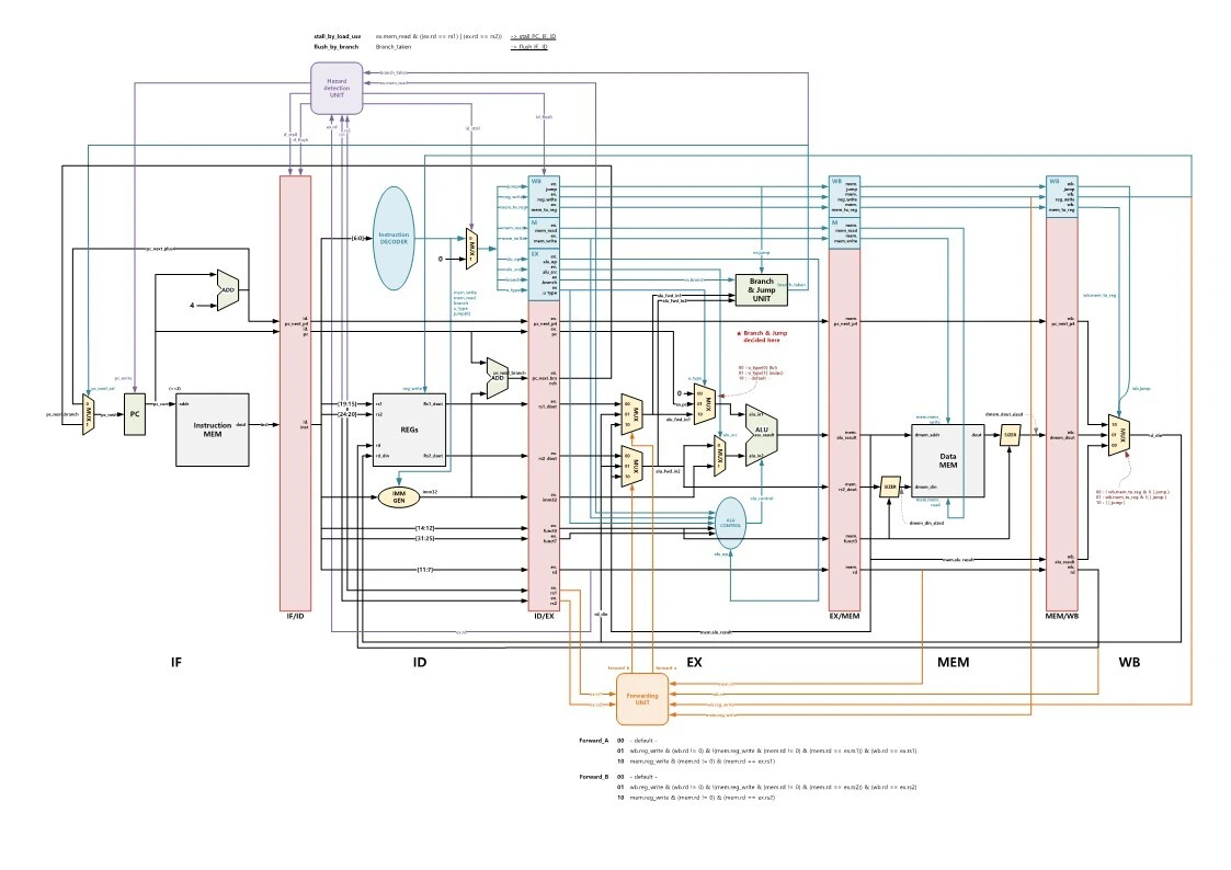
The figure above is a diagram of the 5-stage pipeline that I drew myself. (Please credit the source if you use it :))
Project overview
In this project I designed and implemented, in Verilog, a 5-stage pipelined processor that supports the entire RISC-V RV32I instruction set. Rather than a simple single-cycle processor, it applies the pipelining used in real high-performance CPUs, and it resolves the data hazards and control hazards that pipelining introduces with a hazard detection unit and a forwarding unit.
Simulation was done with iverilog + GTKWave (Linux), and I converted the test programs into machine code by hand and loaded them into the instruction memory.
The RV32I instruction set
RV32I is RISC-V's 32-bit base integer instruction set. It consists of 37 instructions, grouped into the following categories.
- R-Type: register-register operations (ADD, SUB, AND, OR, XOR, SLL, SRL, SRA, SLT, SLTU)
- I-Type: immediate operations and loads (ADDI, ANDI, ORI, LW, LB, LH, JALR)
- S-Type: stores (SW, SB, SH)
- B-Type: conditional branches (BEQ, BNE, BLT, BGE, BLTU, BGEU)
- U-Type: upper immediate loads (LUI, AUIPC)
- J-Type: jump (JAL)
Every instruction is a fixed 32 bits long, and the operation is determined by the combination of the opcode (7 bits), funct3 (3 bits), and funct7 (7 bits) fields. Thanks to the simplicity of the RISC-V specification, the hardware decoder is relatively simple.
The 5-stage pipeline
A pipeline splits instruction execution into five stages so that several instructions are processed at once:
IF (Instruction Fetch)
Fetches the instruction from the instruction memory at the address held in the PC (program counter). Each cycle the PC either increments by 4 or, on a branch, is updated to the branch target.
ID (Instruction Decode)
Decodes the instruction. The opcode determines the instruction type, and the rs1/rs2 register values are read from the register file. The immediate is generated by sign-extending according to the instruction type. The control unit also generates the control signals each stage needs (RegWrite, MemRead, MemWrite, ALUOp, etc.).
EX (Execute)
The ALU performs the actual operation. It handles everything from basic operations such as ADD/SUB/AND/OR/XOR to comparison and shift operations such as SLT (set less than) and SLL (shift left logical). For branch instructions, the condition is evaluated and the branch target computed here.
MEM (Memory Access)
Only load and store instructions use this stage. It sends an address to the data memory and performs the read or write. A load passes the value read from memory to the next stage, while a store writes the rs2 value to memory and is done.
WB (Write Back)
Writes the ALU result or the value read from memory into the rd register of the register file. Only after this stage finishes can other instructions safely read that register.
A single-cycle processor needs the time of all five stages to process one instruction, but with pipelining one instruction completes every cycle, so the theoretical throughput is 5x. In practice hazards keep it from reaching that, but it is still a large performance gain.
Hazard detection unit
The biggest problem in pipelining is hazards. Data hazards are the classic example:
ADD x1, x2, x3   # x1 = x2 + x3
ADD x4, x1, x5   # x4 = x1 + x5 (tries to read x1, but it hasn't been written back yet)
The second instruction can only read the value written to x1 once the first instruction reaches the WB stage. If it reaches EX before then, it reads the stale value.
A load-use hazard is a case that even forwarding cannot resolve:
LW x1, 0(x2)     # x1 = Mem[x2] (value is known in the MEM stage)
ADD x4, x1, x5   # needs x1 (in the EX stage)
In this case, the hazard detection unit checks whether the instruction after a load uses the load's rd as rs1/rs2 and, if so, inserts a one-cycle stall. Specifically, it holds the IF/ID register and the PC at their current values and inserts a NOP (bubble) into the ID/EX register.
Forwarding unit
Most data hazards can be resolved by forwarding, without a stall. Forwarding takes the result of an earlier instruction from where it becomes available (the end of the EX stage or the end of the MEM stage), before it is written to the register file, and sends it directly to the ALU input of the next instruction.
The forwarding unit checks the following conditions to generate the ForwardA and ForwardB signals:
- EX → EX forwarding: RegWrite in the EX/MEM register is 1, EX/MEM.rd != 0, and EX/MEM.rd == ID/EX.rs1 (or rs2)
- MEM → EX forwarding: RegWrite in the MEM/WB register is 1, MEM/WB.rd != 0, the condition above does not apply, and MEM/WB.rd == ID/EX.rs1 (or rs2)
Based on ForwardA/B, the ALU input MUX selects the register value, the EX/MEM result, or the MEM/WB result.
Control hazards
Whether a branch is taken is decided at the end of the EX stage. By then, two instructions have already entered the IF/ID stages, and if the branch is taken, these two are on the wrong path and must be flushed.
In the implementation, when a branch resolves, all control signals in the IF/ID and ID/EX registers are set to 0 so the instructions become NOPs. This costs a 2-cycle penalty per branch. Going further would require branch prediction, but this project simply uses not-taken prediction plus flush.
Waveform analysis
Checking the data in the registers and memory shows that the processor executes the RISC-V instructions correctly. The instructions were converted to machine code and stored in the instruction memory.
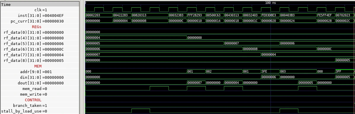
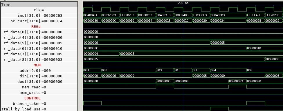
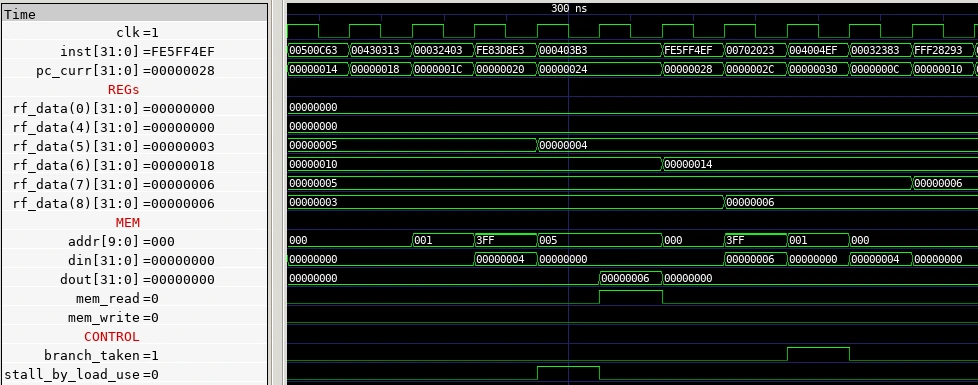
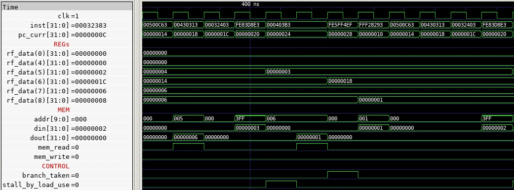
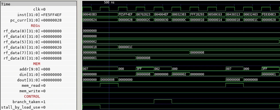
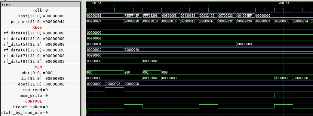
In each waveform I checked the following: that the PC increments correctly every cycle, that instructions pass through the five stages correctly, that the correct value reaches the ALU when forwarding occurs, and that stalls and flushes happen properly when a hazard occurs.
Takeaways
- The complexity of pipelining: The moment you go from single-cycle to pipelined, most of the design effort goes into handling hazards. Performance gains clearly come at a cost.
- The importance of modularity: Building each stage as an independent module and connecting them with pipeline registers made debugging much easier.
- The strength of the RISC-V specification: The instruction formats are consistent, so the decoder is compact. It is in a different league from a variable-length CISC like x86.
- Simulation tools: The iverilog + GTKWave combination is free yet powerful enough. You can learn plenty without the commercial Vivado Simulator.
This project was a great chance to go from start to finish through the process of turning computer architecture theory into real hardware. Watching the textbook five-stage Fetch-Decode-Execute-Memory-Writeback diagram come alive in actual Verilog code and waveforms turned abstract concepts into concrete understanding.