1. Design Requirements
Each team picks its own topic and implements a system on Digilent's Basys3 board. The team combines AHB-Lite Verilog modules to build its own computer system. The team also writes a program for the embedded system in assembly or C, and the computer system must run it. Inputs can take many forms by combining slide switches, buttons, a light sensor, and any modules you want, and outputs can likewise take many forms by combining LED output, 7-segment output, VGA output, analog output, and any modules you want.
2. Design Topic
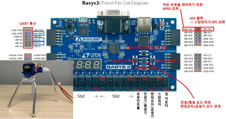
This project has two main topics: a multifunction counter and calculator, and control of a small robot over UART. First, Figure 1 below describes the pins and peripherals of the Basys3 board used in the project. The project uses the board's 15 built-in LEDs, the switches, 5 KEY buttons, and Pmod headers JA and JB. Pmod JA is set up for UART so the board can communicate with another external processor. Pmod JB is used as GPIO, configured so that JB1-4 are inputs and JB7-10 are outputs; in practice, an LED is connected to JB1 and only the JB7 pin is used.
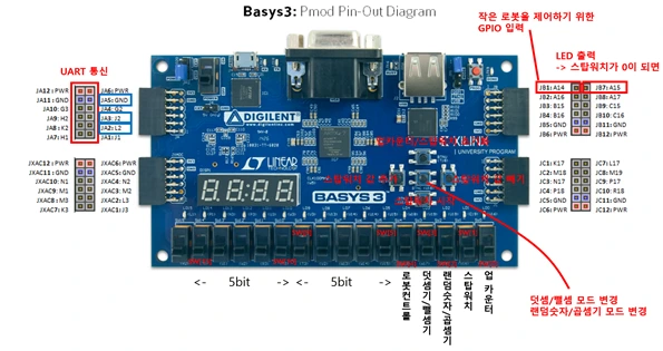
Figure 1 Features implemented with the Basys3's built-in devices and peripheral control through Pmod
As mentioned above, this project uses UART to communicate with and control an external processor, the ESP32-WROOM-32D, a 32-bit, 3.3 V processor. We attached two servo motors to the ESP32-WROOM-32D to build a simple robot, which receives data from the Basys3 to control its movement. Below is the final circuit connecting the ESP32-WROOM-32D and other peripherals to the Basys3.
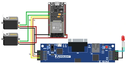
Figure 2 Final project schematic connected to the Basys3 through Pmod
3. Features
The finished design has two main features: a multifunction counter and calculator, and control of a small robot over UART. Each is described separately below.
1) Controlling a Small Robot over UART
To let the Basys3 control a robot made of two servo motors connected to the ESP32-WROOM-32D, we used UART, set up through Pmod pins JA2 and JA3. As the Basys3 reference manual's interface specification in Figure 3 below shows, connecting JA2 as TX and JA3 as RX enabled UART communication.
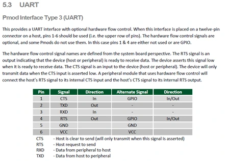
Figure 3 Pmod information from the reference manual
When the ESP32-WROOM-32D receives the robot's on/off state from the Basys3, it drives the connected servo motors through ESP32_Servo.h to move the robot. The Basys3's built-in SW4 serves as the robot control signal, so whether the switch is on determines whether the robot moves.
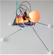
Figure 4 A small robot built with 180-degree servo motors
We built the servo robot as shown in Figure 4 above. When the ESP32-WROOM-32D is powered on, the front-leg and back-leg servos are set to 90 degrees, half of their 180-degree range, to hold a neutral position. After some time to settle, the front-leg servo rotates 20 degrees to the left and then 40 degrees to the right, moving 40 degrees in total across both directions. The back leg moves the same way as the front leg, and operating the servos in sequence lets the robot walk forward.
2) Multifunction Counter and Calculator
The inputs SW[0]–SW[4] select the system's mode.
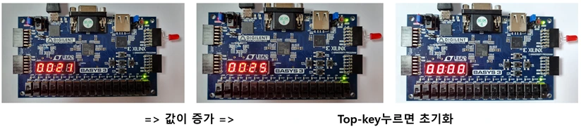
When SW[0] is selected, the system runs as an up counter, incrementing by one through the HW timer. The up-key resets the timer.
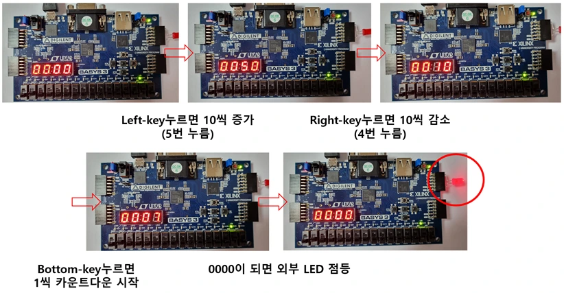
When SW[1] is selected, the system runs as a stopwatch, decrementing by one through the HW timer. The left-key increases the value in steps of ten, and the right-key decreases it in steps of ten. The down-key starts and pauses the stopwatch. The up-key resets the stopwatch. When the stopwatch counts down to 0, an LED blinks through the JB7 pin.
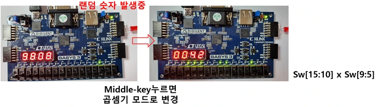
When SW[2] is selected, the system runs as a random number generator/multiplier, either displaying a 4-digit random number or displaying SW[9:5] multiplied by SW[15:10]. Each press of the middle-key switches between random number generator and multiplier mode.
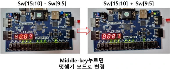
When SW[3] is selected, the system runs as an adder/subtractor, displaying SW[9:5] plus or minus SW[15:10]. Each press of the middle-key switches between add and subtract mode.
When SW[4] is selected, the system is used for robot control, and the robot moves forward when the switch is ON.
4. Design Process
1) H/W Configuration
Basys_Master.xdc
# Switches
set_property PACKAGE_PIN V17 [get_ports {sw[0]}]
	set_property IOSTANDARD LVCMOS33 [get_ports {sw[0]}]
                          ː
set_property PACKAGE_PIN T1 [get_ports {sw[14]}]
	set_property IOSTANDARD LVCMOS33 [get_ports {sw[14]}]
set_property PACKAGE_PIN R2 [get_ports RESET]
	set_property IOSTANDARD LVCMOS33 [get_ports RESET]
# LEDs
set_property PACKAGE_PIN U16 [get_ports {LED[0]}]
set_property IOSTANDARD LVCMOS33 [get_ports {LED[0]}]
ː
set_property PACKAGE_PIN L1 [get_ports {LED[15]}]
set_property IOSTANDARD LVCMOS33 [get_ports {LED[15]}]#7 segment display
set_property PACKAGE_PIN W7 [get_ports {seg[0]}]
set_property IOSTANDARD LVCMOS33 [get_ports {seg[0]}]
ː
set_property PACKAGE_PIN U7 [get_ports {seg[6]}]
set_property IOSTANDARD LVCMOS33 [get_ports {seg[6]}]
set_property PACKAGE_PIN V7 [get_ports dp]
set_property IOSTANDARD LVCMOS33 [get_ports dp]
set_property PACKAGE_PIN U2 [get_ports {an[0]}]
set_property IOSTANDARD LVCMOS33 [get_ports {an[0]}]
ː
set_property PACKAGE_PIN W4 [get_ports {an[3]}]
set_property IOSTANDARD LVCMOS33 [get_ports {an[3]}]#Buttons
set_property PACKAGE_PIN T18 [get_ports KEY[0]]
set_property IOSTANDARD LVCMOS33 [get_ports KEY[0]]
ː
set_property PACKAGE_PIN U18 [get_ports KEY[4]]
set_property IOSTANDARD LVCMOS33 [get_ports KEY[4]]#Pmod Header JA
set_property PACKAGE_PIN L2 [get_ports JATx]
set_property IOSTANDARD LVCMOS33 [get_ports JATx]
set_property PACKAGE_PIN J2 [get_ports JARx]
set_property IOSTANDARD LVCMOS33 [get_ports JARx]#Pmod Header JB
set_property PACKAGE_PIN A14 [get_ports {JBI[0]}]
set_property IOSTANDARD LVCMOS33 [get_ports {JBI[0]}]
ː
set_property PACKAGE_PIN B16 [get_ports {JBI[3]}]
set_property IOSTANDARD LVCMOS33 [get_ports {JBI[3]}]
set_property PACKAGE_PIN A15 [get_ports {JBO[0]}]
set_property IOSTANDARD LVCMOS33 [get_ports {JBO[0]}]
ː
set_property PACKAGE_PIN C16 [get_ports {JBO[3]}]
set_property IOSTANDARD LVCMOS33 [get_ports {JBO[3]}]We modified the xdc file as follows to connect the switches, LEDs, 7-segment display, KEYs, JA Pmod, and JB Pmod used in the project to the board's pins. Pins are enabled by uncommenting them. In the JA Pmod, pins JA2 and JA3 are renamed JATx and JARx and used for UART.
Modules Used
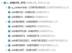
Figure 5 Modules used
Bus Module Definition
module AHBLITE_SYS(
    //CLOCKS & RESET
    input  wire CLK,
    input  wire RESET,

    //TO BOARD LEDs
    output 	wire	[15:0] LED,

    // SW
    input   wire    [14:0]  sw,

    // KEY
    input   wire  [4:0]  KEY,

    // SEG
    output  wire  [6:0]  seg,
    output  wire  [3:0]  an,
    output  wire         dp,

    // UART
    input wire           JARx,
    output wire          JATx,

    // GPIO JB
    input wire  [3:0]   JBI,
    output wire  [3:0]   JBO
);
To set up UART on the Basys3 board, the bus module defines the UART input and output as above. These connect to the Pmod ports modified in the xdc file, and the names must match.
Internal Signal Definitions
//SELECT SIGNALS

wire [3:0] MUX_SEL;
wire HSEL_MEM;
wire HSEL_GPIO;
wire HSEL_KEY;
wire HSEL_SEG;
wire HSEL_TIMER;
wire HSEL_UART;
wire HSEL_GPIO_JB;
The code above defines the SELECT SIGNALS. In the same way, we also defined wires for SLAVE READ DATA and SLAVE HREADYOUT and connected them to the DCD and MUX. This is the usual process, so it is omitted here.
Interrupt Signal Definitions
wire          KEY_IRQ;
wire          TIMER_IRQ;
wire          UART_IRQ;

//CM0-DS INTERRUPT SIGNALS
assign 			  IRQ = {13'b0000_0000_0000_000, KEY_IRQ, UART_IRQ, TIMER_IRQ};
assign 			  LED[15] = LOCKUP;

assign 	      HRESETn = ~RESET;
Interrupt signals come from the Key, Timer, and UART, which handle data, so we defined them as a 16-bit IRQ so the processor can receive interrupt signals.
Modules with Added Interrupts
AHBGPIO uAHBGPIO(
	//AHBLITE Signals
	.HSEL(HSEL_GPIO),
                          ː

	.HRDATA(HRDATA_GPIO),
	.HREADYOUT(HREADYOUT_GPIO),

    .GPIOIN({1'b0, sw[14:0]}),
    .GPIOOUT(LED[14:0])
);
We defined a GPIO module to use the Basys3's built-in switches and LEDs.
AHBGPIO uAHBGPIOJB(
	//AHBLITE Signals
	.HSEL(HSEL_GPIO_JB),
                          ː

	.HRDATA(HRDATA_GPIO_JB),
	.HREADYOUT(HREADYOUT_GPIO_JB),

    .GPIOIN({12'b0, JBI[3:0]}),
    .GPIOOUT(JBO[3:0])
);
We configured the JB Pmod pins as GPIO pins to take inputs from and send outputs to external devices. Each input and output is a 4-bit signal, and this project uses only 1 output bit.
AHB2KEY2 uAHB2KEY2 (
	//AHBLITE Signals
	.HSEL(HSEL_KEY),
                          ː

	.HRDATA(HRDATA_KEY),
	.HREADYOUT(HREADYOUT_KEY),
	//Sideband Signals
	.KEY_IRQ(KEY_IRQ),
	.KEY(KEY)
);
We attached a module to the bus to use the KEYs. The interrupt signal is also connected so the interrupts generated by the KEYs can be received.
//AHBLite Slave

AHBTIMER uAHBTIMER (

//AHBLITE Signals

.HSEL(HSEL_TIMER),

ː

.HRDATA(HRDATA_TIMER),

.HREADYOUT(HREADYOUT_TIMER),

//Sideband Signals

.timer_irq(TIMER_IRQ)

);
We attached the timer module to the bus to use the up counter and stopwatch in the system. A signal for interrupt handling is also connected.
AHBUART uAHBUART (
	//AHBLITE Signals
	.HSEL(HSEL_UART),
                          ː

	.HRDATA(HRDATA_UART),
	.HREADYOUT(HREADYOUT_UART),
	//Sideband Signals
	.JARx(JARx),
	.JATx(JATx),
	.uart_irq(UART_IRQ)
);
We attached the UART module to the bus to communicate with the external robot over UART. It uses Rx and Tx signals, which connect to the JA Pmod. A signal for interrupt handling is also connected.
module BAUDGEN
(
  input wire clk,
  input wire resetn,
  output wire baudtick
);


reg [21:0] count_reg;
wire [21:0] count_next;

//Counter
always @ (posedge clk, negedge resetn)
  begin
    if(!resetn)
      count_reg <= 0;
    else
      count_reg <= count_next;
end


//Baudrate  = 19200 = 50Mhz/(163*16)
assign count_next = ((count_reg == 162) ? 0 : count_reg + 1'b1);

assign baudtick = ((count_reg == 162) ? 1'b1 : 1'b0);

endmodule
Looking at the BAUDGEN module, one of the files under AHBUART, you can find the communication speed, which is important for UART. The comment on the baud rate in the middle of the code states that the speed is set to 19200, and based on this, smooth UART communication with the ESP32-WROOM-32D was possible.
Modifying the KEY Module
module AHB2KEY2(
                          ː
  input wire [4:0] KEY
    );

                          ː

  reg  [4:0] keyout;        //key output

                          ː

  // sequential part
  always @(posedge HCLK or negedge HRESETn)
  begin
	 if(!HRESETn)
   begin
     keyout <= 5'b0;
     key_pushed <= 1'b0;
   end
   else if ((key_pushed == 1'b0) && (KEY != 5'b0))
   begin
     keyout <= KEY;
     key_pushed <= 1'b1;
   end
   else if (KEY == 5'b0)
   begin
     keyout <= 5'b0;
     key_pushed <= 1'b0;
   end
  end

  // sequential part
  always @(posedge HCLK or negedge HRESETn)
  begin
	 if(!HRESETn)
     KEY_IRQ <= 1'b0;
   else if ((key_pushed == 1'b0) && (KEY != 5'b0))
     KEY_IRQ <= 1'b1;
   else if (rd)
     KEY_IRQ <= 1'b0;
  end

                          ː
endmodule
The original KEY module supported only 4 keys, so we modified it as above to use 5.
2) S/W Configuration
cm0dsasm.s
 ː

;Reset Handler
Reset_Handler   PROC
                GLOBAL Reset_Handler
                ENTRY
        IMPORT  __main
                LDR     R0, =__main
                BX      R0                        ;Branch to __main
                ENDP
                      ː
For the project's S/W, we modified the assembly as above so we could use C alongside assembly instead of writing everything in assembly. When Reset_Handler runs, it jumps to main in C.
                      ː
        				; External Interrupts

        				DCD		Timer_Handler
        				DCD		UART_Handler
        				DCD		Key_Handler
                      ː
We defined the addresses of the ISRs that handle each interrupt in the exception vector.
                      ː
Key_Handler     PROC
                EXPORT Key_Handler
				IMPORT  Key_ISR
                PUSH    {R0, R1, R2, R3, LR}
				        BL Key_ISR
                POP     {R0, R1, R2, R3, PC}                    ;return
                ENDP
                      ː
The function above is the KEY interrupt handler, which contains the function that handles the interrupt when it occurs. Here we performed context switching so we could use code written in C. Timer_Handler and UART_Handler are written the same way and omitted here.
edk.driver.h
                      ː
#define AHB_GPIO_JB_BASE		0x50000000
#define AHB_UART_BASE			0x51000000
#define AHB_TIMER_BASE			0x52000000
#define AHB_GPIO_BASE			0x53000000
#define AHB_7SEG_BASE			0x54000000
#define AHB_KEY_BASE			0x55000000
#define NVIC_INT_ENABLE		0xE000E100
                      ː
We defined the addresses for controlling each peripheral. We wrote code to access them through structs, which is omitted here.
                      ː
void seven_seg_write(char dig1, char dig2,char dig3,char dig4);		//Write to 7-segment display
void timer_init(int load_value, int prescale, int mode);			//Initialize the timer
void timer_enable(void);				//Enable the timer
void timer_irq_clear(void);			//Clear interrupt request from timer
int GPIO_read(void);						//GPIO read (from switches)
void GPIO_write(int data);			//GPIO write (to LEDs)
int GPIO_JB_read(void);
void GPIO_JB_write(int data);
                      ː
edk.driver.c defines functions for controlling each driver, listed above. There is a function to write values to the 7-segment display, and functions for timer initialization, enabling, and clearing interrupts. GPIO has 4 functions for reading and writing. Among them, the GPIO_JB functions read and write the JB Pmod used as GPIO.
main.c [Header]
#include "EDK_CM0.h"
#include "core_cm0.h"
#include "edk_driver.h"
#include <stdlib.h>
#include <time.h>
We included the files we use. "" is for files and <> is for libraries. <stdlib.h> and <time.h> are imported so the system can generate random values seeded with the time.
#define Timer_Interrput_Frequency 			1
#define System_Tick_Frequency 					50000000
#define Timer_Prescaler 					1
#define Timer_Load_Value 								(System_Tick_Frequency/Timer_Interrput_Frequency/Timer_Prescaler)
We defined the above to run the timer with a period of 50000000.
// MODE (SW)
#define MODE_UPCOUNTER					0x01
#define MODE_STOPWATCH					0x02
#define MODE_RANDOM_MULTIPLIER	                        0x04
#define MODE_ADDER_SUB					0x08
#define MODE_ROBOT						0x10
SW[4:0] indicates the mode, defined as above. The definitions are based on which switch is turned on. The figure below shows the mode for each switch.
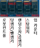
Figure 6 Switch modes
// Function
void delay(unsigned int);
unsigned int knowBit (unsigned int, unsigned int);
unsigned int checkMoreThanTwoSW (unsigned int);
unsigned int cut0to4(unsigned int);
unsigned int cut5to9(unsigned int);
unsigned int cut10to15(unsigned int);
void eachSegmentDivider(unsigned int, unsigned int);
void eachSegmentDivider_all(unsigned int);
void digReset(void);
void diggReset(void);
void inverseBit(unsigned int*);
void increase_dig_4bit(void);
void decrease_dig_4bit(void);
void increase_dig_3bit(void);
void decrease_dig_3bit(void);
We declared the functions used in the system in the header section. Their roles are as follows.
delay(unsigned int period): takes a period variable and delays by that amount using a loop
knowBit (unsigned int temp, unsigned int where): extracts the bit at position [where] from the temp variable
checkMoreThanTwoSW (unsigned int temp): detects whether zero or two or more switches are on
cut0to4(unsigned int temp): extracts [4:0] of temp
cut5to9(unsigned int temp): extracts [9:5] of temp
cut10to15(unsigned int temp): extracts [15:10] of temp
eachSegmentDivider(unsigned int result, unsigned int thousand): splits the result variable into digits so it can be put on the segments; the thousands digit can be set to any value.
eachSegmentDivider_all(unsigned int result): splits the result variable into digits so it can be put on the 7-segment display
digReset(void): resets the dig variables
diggReset(void): resets the digg variables
inverseBit(unsigned int* temp): changes temp to 0 if it is 1, and to 1 if it is 0
increase_dig_4bit(void): increments the 4-digit dig variable by one
decrease_dig_4bit(void): decrements the 4-digit dig variable by one
increase_dig_3bit(void): increments the 3-digit dig variable by one
decrease_dig_3bit(void): decrements the 3-digit dig variable by one
// value
static char dig1,dig2,dig3,dig4;
static char digg1,digg2,digg3,digg4;
static char seven1000, seven100, seven10, seven1;
static unsigned int result;
static unsigned int stopwatchStart;
static unsigned int add_sub_select; // 0: add mode, 1: sub mode
static unsigned int stop_multi_select; // 0: stopwatch mode, 1: multiplier mode
These are the global variables, with the following roles.
dig1,dig2,dig3,dig4: the up counter's count
digg1,digg2,digg3,digg4: the stopwatch's count
seven1000, seven100, seven10, seven1: hold values computed by the system before they are written to the 7-segment display
result: holds the value computed by the system
stopwatchStart: decides whether the stopwatch runs or stops
add_sub_select: selects add or subtract mode (0: add mode, 1: sub mode)
stop_multi_select: selects stopwatch or multiplier mode (0: stopwatch mode, 1: multiplier mode)
main.c [UART_ISR()]
void UART_ISR(void){
	*(unsigned char*) AHB_UART_BASE = knowBit(GPIO_read(),4);
}
This is the UART_ISR function, defined to handle UART interrupts. Here it sends the value of SW[4] over UART.
main.c [Timer_ISR()]
void Timer_ISR(void){
	increase_dig_4bit();

	// MODE_UPCOUNTER
	if(cut0to4(GPIO_read()) == MODE_UPCOUNTER){
		seven_seg_write(dig1, dig2, dig3, dig4);
	}


	// MODE_STOPWATCH
	if(cut0to4(GPIO_read()) == MODE_STOPWATCH){
		decrease_dig_4bit();
		seven_seg_write(digg1, digg2, digg3, digg4);
	}

	// clear JB when not digg:0000
	if(((digg4==0) & (digg3==0) & (digg2==0) & (digg1==0)) != 1){ // 1 is digg all 0000
		GPIO_JB_write(0x00);
	}

	timer_irq_clear();
}
This is the Timer_ISR function, defined to handle timer interrupts. When a timer interrupt occurs, dig is first incremented by one, and in UPCOUNTER mode, it is shown on the 7-segment display. In STOPWATCH mode, it does the opposite and decrements the number by one.
When the count reaches 0 in STOPWATCH mode, an external LED lights up through the GPIO_JB pin. If digg is not 0000, the GPIO_JB pin output is reset to 0 to turn the LED off.
Then the timer's interrupt signal is cleared.
main.c [Key_ISR()]
void Key_ISR(){
  unsigned int temp;
  temp = *(unsigned int*) AHB_KEY_BASE;

  if (temp == 0x1){ // top key:  up-counter reset, stopwatch reset
		digReset();
		diggReset();
                seven_seg_write(0,0,0,0);
		stopwatchStart = 0;
  }
  else if (temp == 0x2){ // left key
		increase_dig_3bit();
		seven_seg_write(digg1, digg2, digg3, digg4);
  }
  else if (temp == 0x4){ // right key
		decrease_dig_3bit();
		seven_seg_write(digg1, digg2, digg3, digg4);
  }
  else if (temp == 0x8){ // bottom key
		inverseBit(&stopwatchStart);
  }
  else if (temp == 0x10){ // middle key
		inverseBit(&add_sub_select);
		inverseBit(&stop_multi_select);
  }
}
This is the Key_ISR function, defined to handle key interrupts. When a key interrupt occurs, we need to check which of the 5 physical keys was pressed. So we used if statements to implement what happens when each of the 5 physical keys is pressed. Here is the explanation.
top key: the button that resets the up counter and stopwatch. It resets the dig and digg variables and resets the 7-segment display to 0000. It also stops the stopwatch by resetting the stopwatch run variable stopwatchStart to 0.
left key: sets the stopwatch time by increasing the tens digit. It increments digg3 by one.
right key: sets the stopwatch time by decreasing the tens digit. It decrements digg3 by one.
bottom key: starts or pauses the stopwatch. This is done with the bit-flipping function. If stop_multi_select is 0, the stopwatch is not running, and if it is 1, it is running.
middle key: switches modes in adder/subtractor mode and random number generator/multiplier mode. This is done with the bit-flipping function. For example, 0 is adder mode and 1 is subtractor mode.
main.c [main()]
int main(void){

	//Initialise timer (load value, prescaler value, mode value)
	timer_init(Timer_Load_Value,Timer_Prescaler,1);
	timer_enable();
	seven_seg_write(0,0,0,0);
	GPIO_JB_write(0x00); //Initialise GPIO_JB
	stopwatchStart = 0;
	add_sub_select=0;
	stop_multi_select=0;

	NVIC_SetPriority (Timer_IRQn, 0x00);
	NVIC_SetPriority (UART_IRQn, 0x80);
	NVIC_SetPriority (KEY_IRQn, 0xC0);
	NVIC_EnableIRQ(Timer_IRQn);			//enable timer interrupt
	NVIC_EnableIRQ(UART_IRQn);			//enable UART interrupt
	NVIC_EnableIRQ(KEY_IRQn);				//enable UART interrupt
                          ː
When main runs, it first performs initialization. It initializes the timer's Timer_Load_Value and Timer_Prescaler and enables the timer. It also resets the 7-segment display to 0, resets the JB Pmod output signal to 0, and initializes variables.
Then it sets the interrupt priorities and enables the interrupts so the system can receive them.
                         ː
	while(1){
		GPIO_write(GPIO_read());

		if (checkMoreThanTwoSW(GPIO_read()) == 0)
			goto nothingHappen;

                          ː

		nothingHappen:
		delay(1000000); // ******
	}
}
main contains a while loop so the program never exits and keeps servicing requests through polling. GPIO_write(GPIO_read()); reads the switches on the Basys3 board and writes them to the onboard LEDs.
checkMoreThanTwoSW(GPIO_read()) returns 0 if zero or two or more of the sw[4:0] mode switches are on, and when it returns 0, the code jumps to the nothingHappen: label so no other function runs. This is because the program gets tangled if the system runs with zero or two or more switches on.
If exactly one mode switch is on, as expected, the goto is not executed and the code below continues.
                          ː
		// MODE_RANDOM_MULTIPLIER
		if (cut0to4(GPIO_read()) == MODE_RANDOM_MULTIPLIER	){
			if(stop_multi_select==0){ // RANDOM MODE
				result = rand() % 10000;
				eachSegmentDivider_all(result);
				seven_seg_write(seven1000, seven100, seven10, seven1);
			}
			else{ // MULTIPLIER MODE
				result = cut5to9(GPIO_read()) * cut10to15(GPIO_read());
				eachSegmentDivider(result, 0x00);
				seven_seg_write(seven1000, seven100, seven10, seven1);
			}
		}
                          ː
When sw[2] is on, the system either outputs a random number or works as a multiplier. Which one depends on the stop_multi_select variable, which toggles each time the middle-key is pressed.
If stop_multi_select is 0, it outputs a random number. We generated the random value with the rand() function from the C stdlib.h library. Since the seed is the time, time.h must also be included. The value is reduced to 4 digits with % 10000 and shown on the 7-segment display.
If stop_multi_select is 1, it works as a multiplier. It extracts sw[9:5] with cut5to9(GPIO_read()) and sw[15:10] with cut10to15(GPIO_read()) and multiplies them. The product is shown on the 7-segment display.
 ː
		// MODE_ADDER_SUB
		else if (cut0to4(GPIO_read()) == MODE_ADDER_SUB){
			if(add_sub_select==0){ // ADDER MODE
				result = cut5to9(GPIO_read()) + cut10to15(GPIO_read());
				eachSegmentDivider(result, 0x00);
				seven_seg_write(seven1000, seven100, seven10, seven1);
			}
			else{ // SUB MODE
				if(cut10to15(GPIO_read())> cut5to9(GPIO_read())){
					result = cut10to15(GPIO_read()) - cut5to9(GPIO_read());
					eachSegmentDivider(result, 0x00);
					seven_seg_write(seven1000, seven100, seven10, seven1);
				}
				else if(cut10to15(GPIO_read())< cut5to9(GPIO_read())){
					result = cut5to9(GPIO_read()) - cut10to15(GPIO_read());
					eachSegmentDivider(result, 0x11); // 0x11 is -
					seven_seg_write(seven1000, seven100, seven10, seven1);
				}
				else{
					seven_seg_write(0,0,0,0);
				}
			}
		}
                          ː
When sw[3] is on, the system works as an adder or subtractor. Which one depends on the add_sub_select variable, which toggles each time the middle-key is pressed.
If add_sub_select is 0, it works as an adder. It extracts sw[9:5] with cut5to9(GPIO_read()) and sw[15:10] with cut10to15(GPIO_read()) and adds them. The sum is shown on the 7-segment display.
If add_sub_select is 1, it works as a subtractor. It extracts sw[9:5] with cut5to9(GPIO_read()) and sw[15:10] with cut10to15(GPIO_read()) and subtracts them. The difference is shown on the 7-segment display.
The subtractor case is handled with if statements: in A-B, if A is larger than B the result is positive and there is no problem, but if B is larger than A, a (-) must be displayed, so we handled it with if statements.
                          ː
		// MODE_ROBOT
		else if (cut0to4(GPIO_read()) == MODE_ROBOT){
			seven_seg_write(0x11,0x11,0x11,0x11);
		}
                          ː
When sw[4] is on, the system runs in ROBOT mode. In this mode, the work is mainly done by the UART interrupt, and the code above shows (- - - -) on the 7-segment display to indicate that the system is in ROBOT mode.
main.c [Functions]
                          ː
void delay(unsigned int period){
	unsigned int counter=0;
	unsigned int i=0;
  for (i=0;i<period;i++){
		counter++;
	}
}
                          ː
This function takes a period variable and delays by that amount using a loop.
  ː
// A function that extracts a specific bit
unsigned int knowBit (unsigned int temp, unsigned int where){
	return (temp & (1 << where)) >> where;
}

// A function that sets a specific bit
unsigned int SetBit (unsigned int temp, unsigned int where){
	return (temp | (1 << where));
}
                          ː
This function extracts the bit at position [where] from the temp variable. It ANDs temp with a value that has a 1 at the desired bit. Conversely, ORing a 1 into the desired bit writes the value.
 ː
// Check if more than two mode SW on => 1: only one, 0: 0 or more than two
unsigned int checkMoreThanTwoSW (unsigned int temp){
	unsigned int i = 0;
	unsigned int check_v = 0;

	while (i < 5){
		if (knowBit(temp, i) == 1)
			check_v ++;
		i ++;
	}

	if (check_v == 1)
		return check_v;
	else
		return 0;
}
                          ː
This function detects whether zero or two or more mode switches are on. It takes temp and loops over each position to check whether it holds a 1. If check_v is 1, exactly one switch is on; any other value means zero or two or more are on, and it returns 0.
                          ː
unsigned int cut0to4(unsigned int temp){
	temp = 0x001F & temp; // 0x001F: 0000 0000 0001 1111
	return temp;
}

unsigned int cut5to9(unsigned int temp){
	temp = 0x03E0 & temp; // 0x03E0: 0000 0011 1110 0000
	return temp >> 5;
}

unsigned int cut10to15(unsigned int temp){
	temp = 0x7C00 & temp; // 0x7C00: 0111 1100 0000 0000
	return temp >> 10;
}
                          ː
These functions extract [4:0], [9:5], and [15:10] of temp, respectively. ANDing with a value that has 1s at the desired bits extracts the desired value.
                          ː
// SegmentDivider -> 3bit + special sign
void eachSegmentDivider(unsigned int result, unsigned int thousand){
	seven1		=	(result) % 10;
	seven10		= (result % 100) /10 ;
	seven100 	= (result %1000) / 100;
	seven1000 =	thousand;
}

// SegmentDivider -> 3bit + special sign
void eachSegmentDivider_all(unsigned int result){
	seven1		=	(result) % 10;
	seven10		= (result % 100) /10 ;
	seven100 	= (result %1000) / 100;
	seven1000 =	(result) / 1000;
}
                          ː
This function splits the result variable into digits so it can be put on the segments. The thousands digit is separated so it can be set to any value. A function that sets the thousands digit separately is needed because a (-) sometimes has to be written to the 7-segment display for a result.
                          ː
void inverseBit(unsigned int* temp){
	if(*temp==0)
		*temp = 1;
	else
		*temp = 0;
}
                          ː
This function changes temp to 0 if it is 1, and to 1 if it is 0. It can be used to switch modes.
                          ː
void digReset(){
	dig1 = 0;
	dig2 = 0;
	dig3 = 0;
	dig4 = 0;
}

void diggReset(){
	digg1 = 0;
	digg2 = 0;
	digg3 = 0;
	digg4 = 0;
}
                          ː
These functions reset the dig and digg variables.
                          ː
void increase_dig_4bit(){
	dig4++;
	if(dig4==10){
		dig4=0;
		dig3++;
		if (dig3==10){
			dig3=0;
			dig2++;
			if (dig2==10){
				dig2=0;
				dig1++;
			}
		}
	}
}

void decrease_dig_4bit(){
	if(stopwatchStart==1){
			if(digg4==0){
				if(digg3==0){
					if(digg2==0){
						if(digg1==0){
							GPIO_JB_write(0x01);
						}
						else{
							digg1--;
							digg2 = 9;
						}
					}
					else{
						digg2--;
						digg3 = 9;
					}
				}
				else{
					digg3--;
					digg4 = 9;
				}
			}
			else
				digg4--;
		}
}
                          ː
These functions increment the 4-digit dig variable by one and decrement the 4-digit dig variable by one, respectively. GPIO_JB_write(0x01); is used to light the external LED when the stopwatch counts down to 0000.
                          ː
void increase_dig_3bit(){
	digg3++;
	if (digg3==10){
		digg3=0;
		digg2++;
		if (digg2==10){
			digg2=0;
			digg1++;
		}
	}
}

void decrease_dig_3bit(){
	if(digg3==0){
		if(digg2==0){
			if(digg1==0){
				// digg: 0000
			}
			else{
				digg1--;
				digg2 = 9;
			}
		}
		else{
			digg2--;
			digg3 = 9;
		}
	}
	else{
		digg3--;
	}
}
                          ː
These functions increase and decrease the tens digit of the dig variable, respectively. When the left and right keys are pressed, they increase and decrease the stopwatch's set time.
ESP32_Servo_UART.ino
#include <ESP32_Servo.h>

Servo frontLegs, backLegs;

int FRONT_Servo = 2;
int BACK_Servo = 4;

void setup() {
  Serial.begin(19200);
  Serial2.begin(19200, SERIAL_8N1, 16, 17);

  frontLegs.attach(FRONT_Servo);
  backLegs.attach(BACK_Servo);
  frontLegs.write(90);  //Center the servo
  backLegs.write(90);   //Center the servo

  delay(5000);  //Wait 5 sec to fix bug legs
}

void loop() {
  if (Serial2.available()) {
    Serial.println(Serial2.read());

    if (Serial2.read() == 1)
      Servo_Work();
    else
      Servo_Wait();
  }
}

void Servo_Work() {
  delay(200);
  frontLegs.write(70);  //move front leg a little
  delay(200);
  backLegs.write(70);  //move back leg a little
  delay(200);
  frontLegs.write(110);  //move front leg a little
  delay(200);
  backLegs.write(110);  //move back leg a little
}


void Servo_Wait() {
  frontLegs.write(90);  //Center the servo
  backLegs.write(90);   //Center the servo
}
For UART communication with the Basys3, we set up UART on the ESP32 in the same way. Serial2.begin(19200, SERIAL_8N1, 16, 17); configures RX pin 16 and TX pin 17 for Serial2 communication, and since the baud rate set on the Basys3 earlier was 19200, we set the same rate on the ESP32. The Basys3 reference manual on UART shows that there is no parity bit, so the ESP32's communication settings also use SERIAL_8N1 mode.
Then Serial2.read() reads the value from the Basys3 over UART to control the motors.
5. Results
Feature 1) Up Counter
Feature 2) Stopwatch
Feature 3) Random Number/Multiplier
Feature 4) Adder/Subtractor
Feature 5) Robot Control
In the Arduino IDE, where the ESP32 code was written, the code below let us see the results of UART communication with the Basys3, and we confirmed that the incoming value changes between 0 and 1 as the Basys3's SW4 is turned on and off.

Figure 7 Checking UART communication with the UART and Serial functions
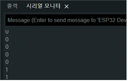
Figure 8 UART results depending on whether the Basys3's SW4 is on
Using this, we controlled the servo motors with the value 0 or 1, and this conditional let us control the robot shown below.
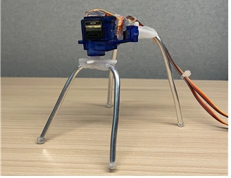
Figure 9 A small robot controlled through the Basys3 and ESP32
6. Discussion
We designed a multifunction counter and calculator and controlled a small robot over UART. We confirmed that everything worked as designed.
Working on the project improved my understanding of the relationship between modules and the bus in ARM HW, and I became confident using each module. Understanding memory-mapped I/O also deepened my understanding of controlling external devices and of external communication methods.
We divided the roles in the project as follows.
Me: Verilog ARM Cortex-M0 HW configuration, system SW implementation
Taeuk Hwang: Verilog ARM Cortex-M0 HW configuration, ESP32-WROOM-32D circuit and code, robot implementation