Chapter 6: Instruction Set Overview
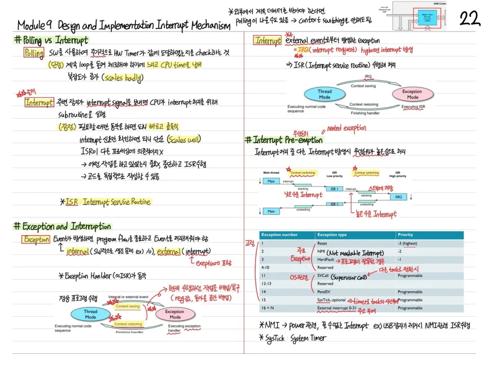
This chapter classifies the Thumb instruction set of the ARM Cortex-M0 by type. It covers categories such as data processing, load/store, branch, and control flow, along with the syntax and encoding of each instruction.
Thumb Instruction Set Categories
The ARM Cortex-M0 supports instructions in the following categories:
- Data processing: ADD, SUB, MUL, AND, ORR, EOR, CMP, MOV
- Data transfer (Load/Store): LDR, STR, LDRB, STRB, LDRH, STRH, LDM, STM
- Branch: B, BL, BX, BLX
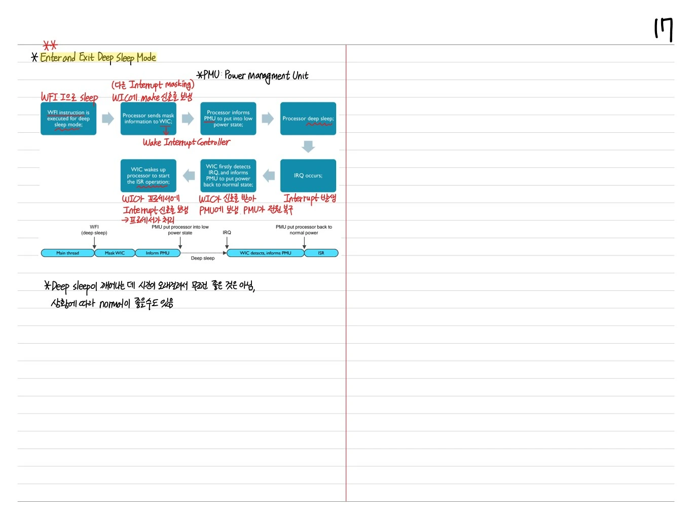
- System: SVC, WFI, WFE, DSB, DMB, ISB, MRS, MSR
Data Processing Instructions
Register-Register
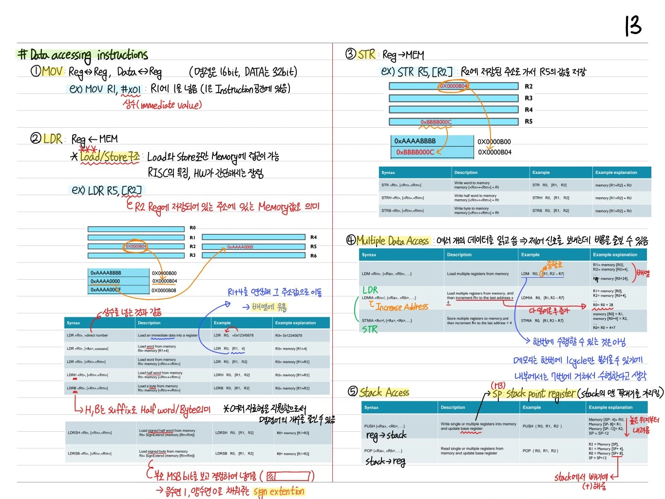
ADD Rd, Rn, Rm: Rd = Rn + RmSUB Rd, Rn, Rm: Rd = Rn - RmADC Rd, Rn: Rd = Rd + Rn + CSBC Rd, Rn: Rd = Rd - Rn - ¬C
Register-Immediate
ADD Rd, #imm: Rd = Rd + imm (0~255 for Rd=R0~R7)SUB Rd, #imm: Rd = Rd - immMOV Rd, #imm: Rd = immCMP Rd, #imm: sets flags only
Logical
AND Rd, Rn: Rd = Rd AND RnORR Rd, Rn: Rd = Rd OR RnEOR Rd, Rn: Rd = Rd XOR Rn (exclusive OR)BIC Rd, Rn: Rd = Rd AND NOT RnMVN Rd, Rn: Rd = NOT RnTST Rn, Rm: sets flags only (AND)
Shift
LSL Rd, Rn, #imm: Logical shift leftLSR Rd, Rn, #imm: Logical shift rightASR Rd, Rn, #imm: Arithmetic shift right (sign-extend)ROR Rd, Rn: Rotate right
Multiply
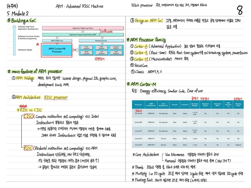
MUL Rd, Rn: Rd = Rd × Rn (32-bit, lower 32-bit only)- Single-cycle or 32-cycle multiplier (optional)
Load/Store Instructions
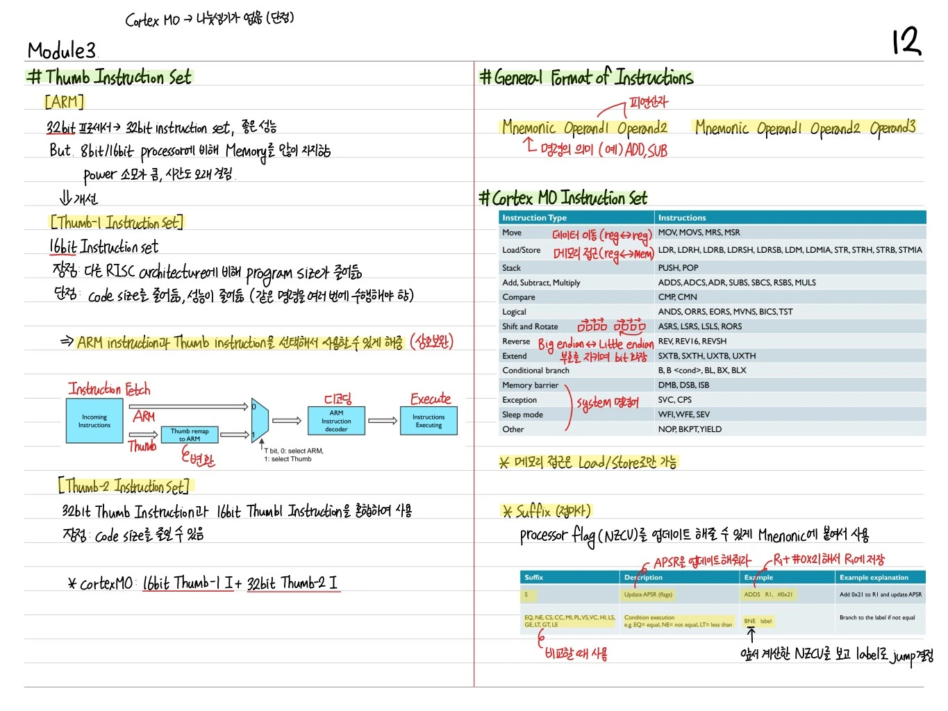
ARM is a load/store architecture: transfers between memory and registers happen only through LDR/STR.
Basic
LDR Rt, [Rn, #imm]: Rt = mem[Rn + imm] (word, 32-bit)STR Rt, [Rn, #imm]: mem[Rn + imm] = RtLDRB Rt, [Rn, #imm]: byte load (zero-extended)STRB Rt, [Rn, #imm]: byte storeLDRH Rt, [Rn, #imm]: halfword loadSTRH Rt, [Rn, #imm]: halfword storeLDRSB,LDRSH: signed byte/halfword load
Register Offset
LDR Rt, [Rn, Rm]: Rt = mem[Rn + Rm]
Multiple Load/Store
LDMIA Rn!, {Rlist}: start at Rn, load the register list in order, update RnSTMIA Rn!, {Rlist}: the store versionPUSH {Rlist}: push onto the stack (STMDB SP!, {Rlist})POP {Rlist}: pop from the stack (LDMIA SP!, {Rlist})
PC-Relative Load
LDR Rt, [PC, #imm]: load from a constant table
Branch Instructions
Unconditional Branch
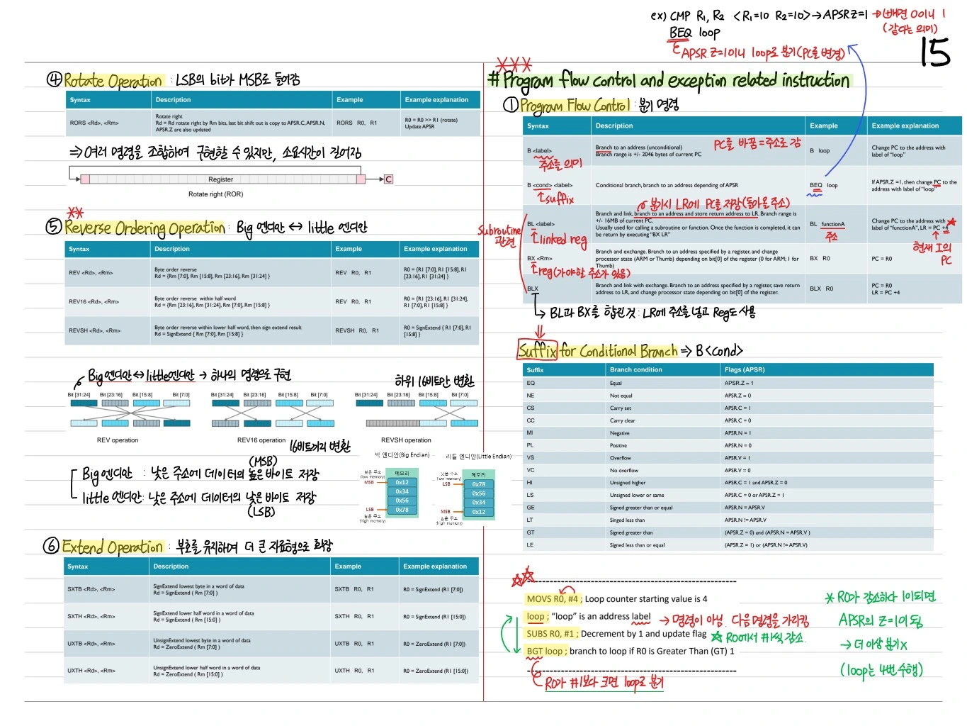
B label: PC = label (±2 KB)BL label: LR = PC+4, PC = label (±16 MB), a function callBX Rm: PC = Rm (register indirect, Thumb/ARM state switch)BLX Rm: LR = PC+4, PC = Rm
Conditional Branch
B{cond} label: branches only when the condition is true- BEQ, BNE, BCS/BHS, BCC/BLO, BMI, BPL, BVS, BVC
- BHI, BLS, BGE, BLT, BGT, BLE
Return from Subroutine
BX LR: return from a function (to the address saved in LR)POP {PC}: restore the PC from the stack
System Instructions
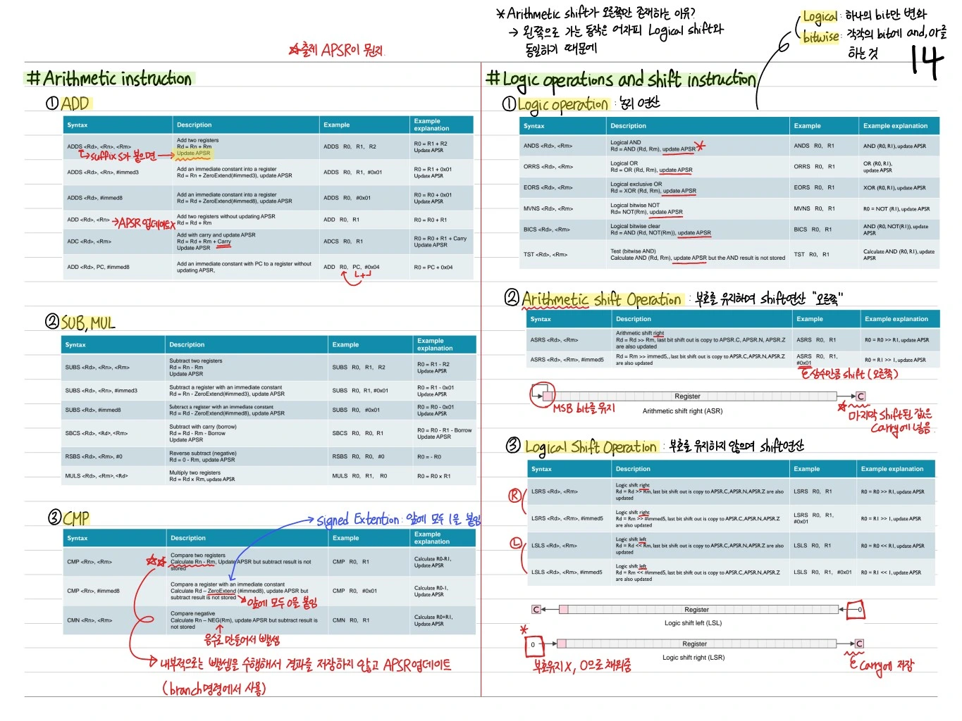
SVC #imm: Supervisor Call (OS service)WFI: Wait For Interrupt (sleep)WFE: Wait For EventSEV: Send EventDMB: Data Memory BarrierDSB: Data Synchronization BarrierISB: Instruction Synchronization Barrier
Status Register Access
MRS Rd, <reg>: Read special register (APSR, IPSR, EPSR, MSP, PSP, PRIMASK, CONTROL)MSR <reg>, Rn: Write special register
Miscellaneous
NOP: No Operation (pipeline bubble)BKPT #imm: Breakpoint (debug)YIELD: Multi-threading hintREV Rd, Rn: Reverse byte order in word (endian swap)REV16,REVSH: swap in halfword units
Setting Constants
- A 32-bit constant is assembled with MOVS + LDR [PC, ...] or with several instructions
- Thumb-2 loads it 16 bits at a time with MOVW/MOVT
Example
MOV R0, #0x12       ; R0 = 0x12
LSL R0, R0, #24     ; R0 = 0x12000000
ADD R0, #0x34       ; R0 = 0x12000034
Or with the LDR pseudo-instruction:
LDR R0, =0x12345678 ; the assembler creates a literal pool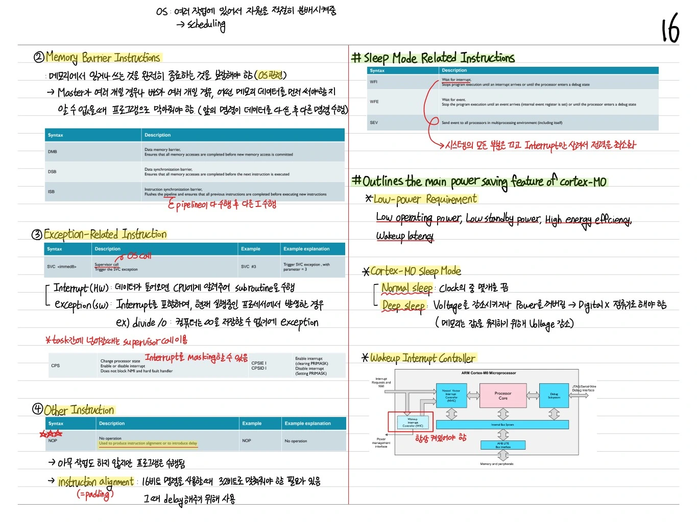
Encoding Format
A 16-bit Thumb instruction consists of an opcode + register fields + an immediate.
Example: encoding of ADD R0, R1, R2:
- opcode[15:9]:
0001100 - Rm[8:6]: R2
- Rn[5:3]: R1
- Rd[2:0]: R0
A 32-bit Thumb-2 instruction consists of two 16-bit words. If the top 5 bits of the first word are 11101, 11110, or 11111, the instruction is 32-bit.
Summary
| Category | Examples |
|---|---|
| Data processing | ADD, SUB, MUL, AND, ORR, LSL, LSR |
| Load/Store | LDR, STR, PUSH, POP, LDMIA, STMIA |
| Branch | B, BL, BX, B{cond} |
| System | SVC, WFI, DMB, MRS, MSR |
| Misc | NOP, BKPT, REV |
ARM Cortex-M0 Thumb instructions are simple and fixed-length (16-bit), so they are easy to decode and give good code density. Most embedded code can be written with this instruction set alone.