1. Design description
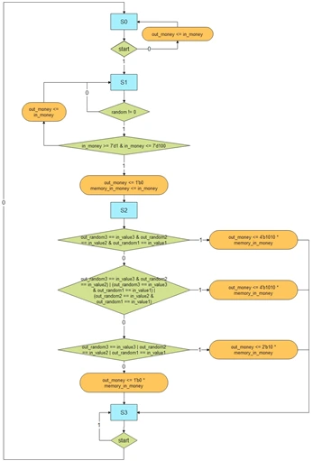
First, when the start signal is 0, the output is the input multiplied by 1, and the three random values are initialized to 000. When the start signal is 1, the slot machine operates as follows. A timer is used to give a seed value to a linear feedback shift register, which is then used to output three random values from 0 to 9, each as a 4-bit binary number in BCD form. The input can be a decimal number from 1 to 100, given as a 7-bit binary input. If all three 4-bit BCD numbers match, the output is 10x the input; if two numbers match, 5x; and if one number matches, 2x, output in binary form.
2. Block diagram and sub-block definitions
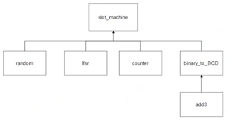
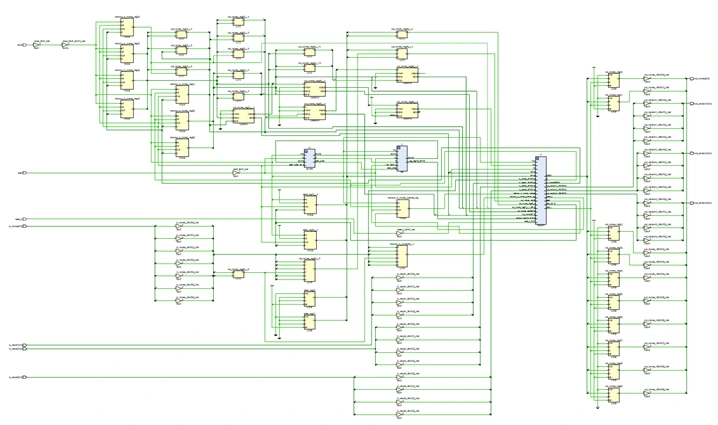
1) Block diagram
2) Sub-blocks
(1) random module
module random (clock, reset_b, start, q, random);
    input wire clock, reset_b, start;
    input wire [15:0] q;
    output reg [15:0] random;

    parameter magic = 16'd6;

    reg [15:0] count;
    reg randomed;

    always @(posedge clock, negedge reset_b)
    begin
        if (~reset_b) begin
            count <= 16'b0;
            random <= 16'b0;
            randomed <= 1'b0;
        end
        else if (~start) begin
            count <= 16'b0;
            random <= 16'b0;
            randomed <= 1'b0;
        end
        else if (start & (count == magic) & ~randomed) begin
            count <= count;
            random <= q;
            randomed <= 1'b1;
        end
        else begin
            count <= count + 1;
            random <= random;
            randomed <= randomed;
        end
    end
endmoduleInputs: clock, reset_b, start, q
Outputs: random
random is a module that takes clock, reset_b, start, and q as inputs and outputs a random value. q is the output of the lfsr, a 16-bit random value. q changes on every posedge. This is covered in detail in the description of the lfsr module.
The parameter magic makes the q of the lfsr module change 6+1 times. In other words, it lets the value that comes out after the lfsr module runs 7 times, after 7 posedges, become the output of random. count increases from 0 to magic, as can be seen in the else clause. Also, once count reaches 7, randomed becomes 1 and the process does not repeat.
The magic value is arbitrary; if you want to mix 15 times, set it to 14.
(2) lfsr module
module lfsr (clock, reset_b, seed_pulse, count, q);
    input wire clock, reset_b, seed_pulse; // seed_pulse: used to apply the seed exactly once
    input wire [15:0] count;

    output wire [15:0] q;

    reg [15:0] r_reg;
    wire [15:0] r_next;
    wire feedback_value;

    always @(posedge clock, negedge reset_b)
    begin
        if (~reset_b)
            r_reg <= 16'b1;
        else if (seed_pulse)
            r_reg <= count;
        else
            r_reg <= r_next;
    end

    assign feedback_value = r_reg[13] ^ r_reg[4] ^ r_reg[0]; //lfsr mixing function

    assign r_next = {feedback_value, r_reg[15:1]};
    assign q = r_reg;
endmoduleInputs: clock, reset_b, seed_pulse, count
Outputs: q
It takes clock, reset_b, seed_pulse, and count as inputs and produces q as output. The output q is used as an input of the random module above.
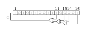
An lfsr is a linear feedback shift register. It is a kind of shift register in which the value entering the register is computed as a linear function of its previous state values. The linear function used is usually exclusive OR (XOR). The initial bit value of an LFSR is called the seed. Because an LFSR operates deterministically, the sequence of values it generates is determined by its previous values. Also, since the number of values the register can hold is finite, the sequence repeats with a certain period. But with a well-chosen linear function, it can generate a sequence that has a long period and looks random. In other words, it can produce random numbers.
The list of bit positions that affect the next state is called the tap sequence. Here I chose 13, 4, and 0. Choosing other values is fine too; only the mixing scheme, i.e. the mixing equation, changes.
The seed value has to be applied only once, when the lfsr starts operating. seed_pulse is used to implement this. seed_pulse comes from the counter module. How it is applied only once is described in the counter module. feedback_value is the mixed value; it goes into bit [15] of the linear register, and the value that was in [0] is shifted out and lost. In the code above this is described with an assign statement as r_next. In other words, on every clock, the mixed value enters [15] and everything shifts down by one position. The random value produced this way is assigned to r_reg and then to q, becoming the output.
In the random module above, magic determines how many times this lfsr runs, i.e. how many times it mixes. Since it operates on the clock posedge, that number equals the number of clocks.
The counter value is used as the lfsr seed. That is, after the system starts the counter keeps increasing, and when start becomes 1 the counter value goes into the lfsr. As explained above, this happens only once until a reset.
(3) counter
module counter (clock, reset_b, start, count, seed_pulse);
    input wire clock, reset_b, start;
    output reg [15:0] count;
    output reg seed_pulse;

    always @(posedge clock, negedge reset_b)
    begin
        if (~reset_b)
            count <= 16'b0;
        else
            count <= count + 1;
    end

    reg pushed;

    // useful for firing exactly once
    // set pushed <stays 1 until start becomes 0; when start becomes 0, pushed is cleared to 0>
    always @(posedge clock, negedge reset_b)
    begin
        if (~reset_b)
            pushed <= 1'b0;
        else if (~pushed & start)
            pushed <= 1'b1;
        else if (~start)
            pushed <= 1'b0;
    end

    // generate seed_pulse  => seed_pulse becomes 1 exactly once when start becomes 1, and stays 0 otherwise
    always @(posedge clock, negedge reset_b)
    begin
        if (~reset_b) // reset:1
            seed_pulse <= 1'b0;
        else if (~pushed & start) // pushed:0 start:1  => when start changes from 0 to 1, pushed is 0, so this happens exactly once
            seed_pulse <= 1'b1;
        else // pushed:1
            seed_pulse <= 1'b0;
    end
endmoduleInputs: clock, reset_b, start
Outputs: count, seed_pulse
The first always block describes a counter that increments with the clock. There is also seed_pulse, which gives the lfsr its seed value exactly once, and an always block that creates pushed, which is used to create seed_pulse.
pushed is set to 0 when start is 0 or reset_b is 0, and set to 1 when pushed is 0 and start is 1. In other words, when pushed is 0 and start becomes 1, seed_pulse becomes 1. After that, pushed is 0 again when start becomes 1, so it fires only once.
(4) binary to BCD
module binary_to_BCD(binary, digit10000, digit1000, digit100, digit10, digit0);
    input [15:0] binary;
    output reg [3:0] digit10000, digit1000, digit100, digit10, digit0;
    wire [3:0] c1,c2,c3,c4,c5,c6,c7,c8,c9,c10,c11,c12,c13,c14,c15,c16,c17,c18,c19,c20,c21,c22,c23,c24,c25,c26,c27,c28,c29,c30,c31,c32,c33,c34; // add3's output
    reg [3:0] d1,d2,d3,d4,d5,d6,d7,d8,d9,d10,d11,d12,d13,d14,d15,d16,d17,d18,d19,d20,d21,d22,d23,d24,d25,d26,d27,d28,d29,d30,d31,d32,d33,d34; // add3's input

    add3 a1(d1,c1); add3 a2(d2,c2); add3 a3(d3,c3); add3 a4(d4,c4); add3 a5(d5,c5);
    add3 a6(d6,c6); add3 a7(d7,c7); add3 a8(d8,c8); add3 a9(d9,c9); add3 a10(d10,c10);
    add3 a11(d11,c11); add3 a12(d12,c12); add3 a13(d13,c13); add3 a14(d14,c14); add3 a15(d15,c15);
    add3 a16(d16,c16); add3 a17(d17,c17); add3 a18(d18,c18); add3 a19(d19,c19); add3 a20(d20,c20);
    add3 a21(d21,c21); add3 a22(d22,c22); add3 a23(d23,c23); add3 a24(d24,c24); add3 a25(d25,c25);
    add3 a26(d26,c26); add3 a27(d27,c27); add3 a28(d28,c28); add3 a29(d29,c29); add3 a30(d30,c30);
    add3 a31(d31,c31); add3 a32(d32,c32); add3 a33(d33,c33); add3 a34(d34,c34);

    always @ (*) begin
        // 1st vertical line from right
        d1 <= {1'b0, binary[15:13]};
        d2 <= {c1[2:0], binary[12]};
        d3 <= {c2[2:0], binary[11]};
        d4 <= {c3[2:0], binary[10]};
        d5 <= {c4[2:0], binary[9]};
        d6 <= {c5[2:0], binary[8]};
        d7 <= {c6[2:0], binary[7]};
        d8 <= {c7[2:0], binary[6]};
        d9 <= {c8[2:0], binary[5]};
        d10 <= {c9[2:0], binary[4]};
        d11 <= {c10[2:0], binary[3]};
        d12 <= {c11[2:0], binary[2]};
        d13 <= {c12[2:0], binary[1]};

        // 2nd vertical line from right
        d14 <= {1'b0, c1[3], c2[3], c3[3]};
        d15 <= {c14[2:0], c4[3]};
        d16 <= {c15[2:0], c5[3]};
        d17 <= {c16[2:0], c6[3]};
        d18 <= {c17[2:0], c7[3]};
        d19 <= {c18[2:0], c8[3]};
        d20 <= {c19[2:0], c9[3]};
        d21 <= {c20[2:0], c10[3]};
        d22 <= {c21[2:0], c11[3]};
        d23 <= {c22[2:0], c12[3]};

        // 3rd vertical line from right
        d24 <= {1'b0, c14[3], c15[3], c16[3]};
        d25 <= {c24[2:0], c17[3]};
        d26 <= {c25[2:0], c18[3]};
        d27 <= {c26[2:0], c19[3]};
        d28 <= {c27[2:0], c20[3]};
        d29 <= {c28[2:0], c21[3]};
        d30 <= {c29[2:0], c22[3]};

        // 4th vertical line from right
        d31 <= {1'b0, c24[3], c25[3], c26[3]};
        d32 <= {c31[2:0], c27[3]};
        d33 <= {c32[2:0], c28[3]};
        d34 <= {c33[2:0], c29[3]};

        // output
        digit0 <= {c13[2:0], binary[0]};
        digit10 <= {c23[2:0], c13[3]};
        digit100 <= {c30[2:0], c23[3]};
        digit1000 <= {c34[2:0], c30[3]};
        digit10000 <= {c31[3], c32[3], c33[3], c34[3]};
    end
endmodule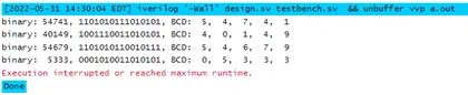
Inputs: binary
Outputs: digit10000, digit1000, digit100, digit10, digit0
This describes a binary to BCD circuit, i.e. one that converts a binary number to BCD. BCD is a numbering scheme that groups four binary digits to represent one decimal digit. The conversion works as follows.
① Process the binary value by shifting it in bit by bit, starting from the MSB
② If a digit is greater than or equal to 5, add 3 and then shift
③ If it is less than 5, shift without adding 3
Written with a for loop, it looks like the code below. However, since the for loop is not synthesizable, I rewrote it directly as combinational logic, as in the figure below.
module bin2bcd(
   input [13:0] bin,
   output reg [15:0] bcd
   );

integer i;

always @(bin) begin
    bcd=0;
    for (i=0;i<14;i=i+1) begin                  //Iterate once for each bit in input number
        if (bcd[3:0] >= 5) bcd[3:0] = bcd[3:0] + 3;     //If any BCD digit is >= 5, add three
    if (bcd[7:4] >= 5) bcd[7:4] = bcd[7:4] + 3;
    if (bcd[11:8] >= 5) bcd[11:8] = bcd[11:8] + 3;
    if (bcd[15:12] >= 5) bcd[15:12] = bcd[15:12] + 3;
    bcd = {bcd[14:0],bin[13-i]};                //Shift one bit, and shift in proper bit from input
    end
end
endmodule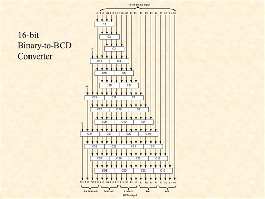
I wrote a test bench to check it and confirmed that the results came out correctly. Since the binary is 16 bits, converting it to BCD gives 5 digits. We need only 3 digits, so the rest can be discarded. In Verilog it's fine to leave a wire unconnected, so in the main module I left them floating. But since the role of this 16-bit binary to BCD module is to output 5 digits, I kept the output at 5 digits so it can be instantiated at any time and the code can be reused.
(5) add3
module add3(in,out);
    input [3:0] in;
    output [3:0] out;
    reg [3:0] out;

    always @ (in)
    case (in)
        4'b0000: out <= 4'b0000;
        4'b0001: out <= 4'b0001;
        4'b0010: out <= 4'b0010;
        4'b0011: out <= 4'b0011;
        4'b0100: out <= 4'b0100;
        4'b0101: out <= 4'b1000;
        4'b0110: out <= 4'b1001;
        4'b0111: out <= 4'b1010;
        4'b1000: out <= 4'b1011;
        4'b1001: out <= 4'b1100;
        default: out <= 4'b0000;
    endcase
endmodule
This module is a submodule used in the binary to BCD module. It is an adder that adds 3 if the value exceeds 5 [0101(2)]. For example, 7 [0111(2)] -> 10 [1010(2)]: 7 exceeds 5, so it outputs 10, which is 7 plus 3.
3) Main block
module slot_machine (clock, start, reset_b, in_value1, in_value2, in_value3, in_money, out_random3, out_random2, out_random1, out_money);
    input wire clock, start, reset_b;
    input wire [3:0] in_value1, in_value2, in_value3;
    input wire [6:0] in_money;
    output wire [3:0] out_random3, out_random2, out_random1; // only the last 3 of the 5 BCD digits are used
    output reg [9:0] out_money;
The inputs and outputs are as above. in_value1, in_value2, and in_value3 are the values the slot machine user enters; they are compared with the random values, and if the numbers match, the corresponding amount of money is output. The user's in_money is also taken as an input.
out_random1, out_random2, and out_random3 are the generated random values, designated as outputs to show them to the user. A value called out_money is also set as an output to return money to the user.
    // connection
    reg [2:0] state;
    reg [2:0] next_state;
    reg [6:0] memory_in_money;
    reg memory_in_money_pushed;

    // parameter
    parameter S0 = 2'd0, S1 = 2'd1, S2 = 2'd2, S3 = 2'd3;

    // wire
    wire [15:0] random;
    wire [15:0] q; // output of the lfsr module, input of the random module
    wire seed_pulse; // 1-bit seed pulse => value from the clock module "marks the one-time execution"
    wire [15:0] count; // count value from the counter module, used as the lfsr seed
    wire [3:0] digit1000, digit10000; //leftover values (BCD thousands and ten-thousands digits)

    // instantiation
    random r1 (clock, reset_b, start, q, random);
    lfsr l1 (clock, reset_b, seed_pulse, count, q);
    counter c1 (clock, reset_b, start, count, seed_pulse);
    // binary_to_BCD instance: takes the 16-bit random value from the random module and extracts 5 BCD digits
    binary_to_BCD btb1 (.binary(random), .digit10000(digit10000), .digit1000(digit1000), .digit100(out_random3), .digit10(out_random2), .digit0(out_random1));
state and next_state under the connection comment are of reg type and hold the current state and next state, respectively. memory_in_money is used to store the value of in_money at the moment start becomes 1, provided a valid value from 1 to 100 has been entered. memory_in_money_pushed is used to store it only once, because if the money kept being stored, the value would change.
       // runs only on the rising clock edge; resets at any time when reset_b receives 1
    always @ (posedge clock, negedge reset_b)
    begin
        if (~reset_b) // reset_b:0 -> reset state
            state <= S0;
        else // normally state changes to the next state
            state <= next_state;
    end
This is used to change the current state to the next state when the value of next_state changes. With this state value, state changes can be described below with a case statement. A statement that resets the state if reset_b becomes 0 is also included.
   // when start:1 and 1<=in_money<=100, store in_money into memory_in_money exactly once
    always @(posedge clock, negedge reset_b)
    begin
        if (~reset_b) begin
            memory_in_money_pushed <= 1'b0;
            memory_in_money <= 7'b0;
        end
        else if ((in_money >= 7'd1 & in_money <= 7'd100) & random == 0 & ~memory_in_money_pushed & start) begin
            memory_in_money_pushed <= 1'b1;
            memory_in_money <= in_money;

        end
        else if (~start) begin
            memory_in_money_pushed <= 1'b0;
            memory_in_money <= 7'b0;
        end
    end
in_money must have a value from 1 to 100, and if any other value comes in as input, the machine must wait until a valid value arrives. When a valid value arrives, it is stored in memory_in_money through memory_in_money_pushed.
   // state transition description
    always @ (*)
    begin
        case(state)
            S0: begin
                if (~start) begin
                    out_money <= in_money;
                    next_state <= S0;
                end
                else begin // start: 1
                    out_money <= in_money;
                    next_state <= S1;
                end
            end
This describes the S0 state. It simply waits until start becomes 1, passing the input money straight through to the output.
		     S1: begin
                if (random != 0)begin
                    next_state <= S2; // move to S2 only after a random value has arrived
                end
                else if (in_money == 0 | in_money > 7'd100 & random == 0) begin // when money in 1~100 has not been entered
                    next_state <= S1;
                    out_money <= in_money;
                end
                else if ((in_money >= 7'd1 & in_money <= 7'd100) & random == 0) begin // when money is in 1~100 and random is 0
                    out_money <= 1'b0;
                    next_state <= S1;
                end

            end
This describes the S1 state. The if statements split it into several cases. First, if the random value is 0, it stays in S1. The reason is that the random value must arrive before it can be compared with the value the user entered. The comparison state is S3, and entering S3 while the random value is 0 would cause a comparison against a wrong value. While staying in S1, it waits until in_money receives a value from 1 to 100.
            S2: begin
                if (out_random3 == in_value3 & out_random2 == in_value2 & out_random1 == in_value1) begin
                    out_money <= 4'b1010 * memory_in_money;
                    next_state <= S3;
                end
                else if ((out_random3 == in_value3 & out_random2 == in_value2) | (out_random3 == in_value3 & out_random1 == in_value1) | (out_random2 == in_value2 & out_random1 == in_value1)) begin
                    out_money <= 4'b101 * memory_in_money;
                    next_state <= S3;
                end
                else if (out_random3 == in_value3 | out_random2 == in_value2 | out_random1 == in_value1) begin
                    out_money <= 2'b10 * memory_in_money;
                    next_state <= S3;
                end
                else begin
                    out_money <= 1'b0 * memory_in_money;
                    next_state <= S3;
                end
            end
The S2 state compares each digit and sets out_money according to the conditions. If all three binary numbers match, the output is 10x the input; if two numbers match, 5x; and if one number matches, 2x, output in binary form. It then moves to the next state, S3.
            S3: begin // prevents going to S0 while start is 1
                if (~start) // start:0 -> move to S0
                    next_state <= S0;
                else begin
                    next_state <= S3;
                    out_money <= 7'b0;
                end
            end
            default state <= S0;
        endcase
    end
endmodule
In S3, the machine checks whether start is 0 or 1. If it went to S0 while start was 1, it would move straight on to S1 and fail to reset, so this prevents that.
4. Simulation
module tb;

    reg clock, reset_b, start;

    wire [15:0] count, q, random;
    wire seed_pulse;

    reg [3:0] in_value1, in_value2, in_value3;
    reg [6:0] in_money;
    wire [3:0] out_random3, out_random2, out_random1;
    wire [9:0] out_money;

    slot_machine sm1 (clock, start, reset_b, in_value1, in_value2, in_value3, in_money, out_random3, out_random2, out_random1, out_money);

    counter c1 (clock, reset_b, start, count, seed_pulse);
    lfsr c2 (clock, reset_b, seed_pulse, count, q);
    random c3 (clock, reset_b, start, q, random);

    initial
    clock = 0;
    always
    #5 clock = ~clock;

    initial
    begin
        reset_b = 0; // 0
        #10 reset_b =1; //10
        #380 reset_b = 0;
    end

    initial
    begin
        start = 0;
        #40 start =1;
        #100 start = 0;
        #80 start =1;
        #100 start = 0;
        #50 start = 1;
        #55 $finish;
    end

    initial
    begin
        in_value3 = 4'd1; in_value2 = 4'd3; in_value1 = 4'd4;
        #20 in_value3 = 4'd2; in_value2 = 4'd3; in_value1 = 4'd4;
        #70 in_value3 = 4'd2; in_value2 = 4'd3; in_value1 = 4'd4;
        #70 in_value3 = 4'd4; in_value2 = 4'd2; in_value1 = 4'd1;
        #100 in_value3 = 4'd4; in_value2 = 4'd4; in_value1 = 4'd1;
        #100 in_value3 = 4'd2; in_value2 = 4'd0; in_value1 = 4'd1;
    end

    initial
    begin
        in_money = 7'b1110;
        #10 in_money = 7'b11010;
        #30 in_money = 7'b111_1111;
        #20 in_money = 7'b1_1011;
        #10 in_money = 7'b0;
        #90 in_money = 7'b110;
        #20 in_money = 7'b1_1011;
        #60 in_money = 7'b0;
        #150 in_money = 7'b110;
    end

    initial
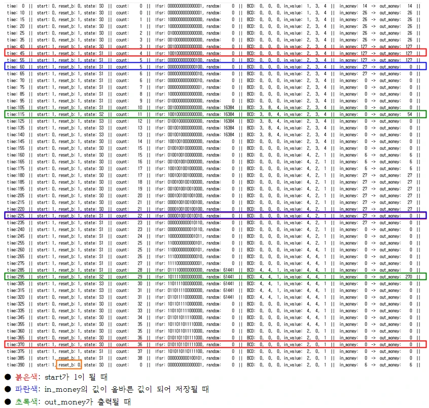
    $monitor("time:%3d  ||  start: %b, reset_b: %b, state: S%d  ||  count: %d  ||  lfsr: %b, random: %d  ||  BCD: %d, %d, %d, in_value: %d, %d, %d  ||  in_money: %d  ->  out_money: %d  ||", $time, start, reset_b, sm1.state, count, q, random, out_random3, out_random2, out_random1, in_value3, in_value2, in_value1, in_money, out_money);
endmodule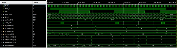

5. Discussion
I described a timer-based slot machine in the Verilog HDL. Along the way I learned about lfsrs and how random values are generated. Practicing how to describe sequential circuits also gave me a much better understanding of them, and I felt my ability to describe circuits improve.
The results can be seen in the simulation. When the red start signal is applied, the timer's seed value is correctly applied to the lfsr. Then, once the clock has run for the set magic value, i.e. once the lfsr has been mixed the set number of times, the random value is output, and the lowest 3 digits of its BCD conversion are compared with in_value. With an input of 27, one digit matches, so double the money is output.
I also confirmed that when 127 is entered as money, it is not within 1 to 100, so the machine waits for input again.
On the second start, an input of 27 was received, and all three digits matched, so 270, ten times the input, was output.
Finally, when reset_b becomes 0, the asynchronous reset is executed and every value is initialized. Since the machine must not take the money at this point, the money input is passed straight through to the output.
Based on these results, I completed a design that satisfies the given specification.