Chapter 8: Hardware Hacking Overview
This chapter covers how to control external devices directly from a Raspberry Pi using GPIO, UART, I2C, and SPI, up to an exercise that lights an LED by manipulating the BCM2835 peripheral registers directly.
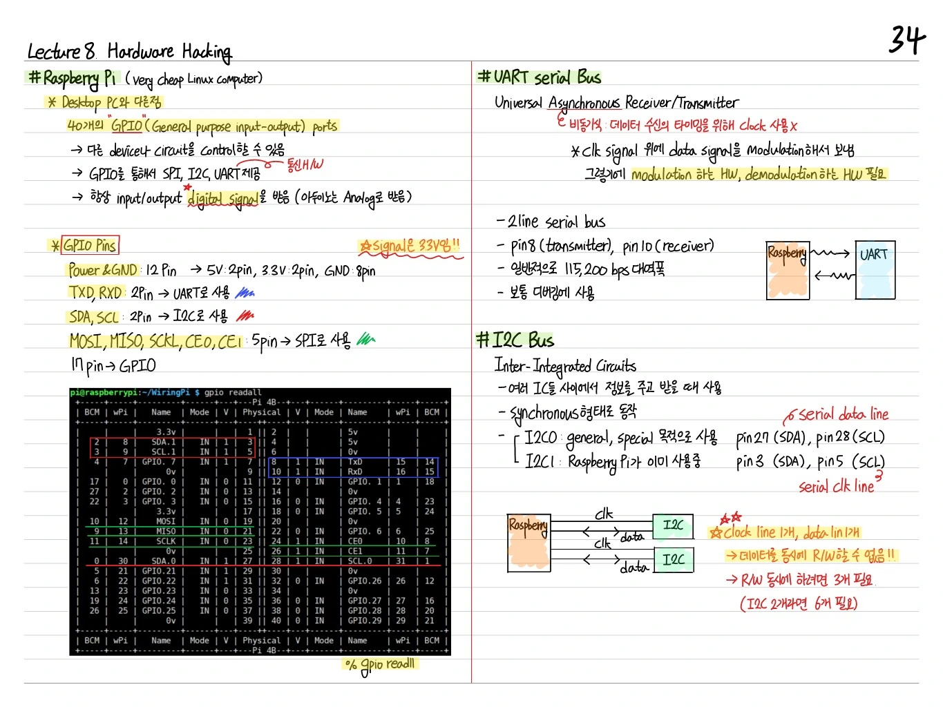
Raspberry Pi (+ Linux computer)
- The Raspberry Pi supports several serial/parallel I/O interfaces, including GPIO, UART, SPI, and I2C
- It runs Linux, so they are easy to reach from the shell
GPIO (General Purpose I/O)
- Digital I/O pins: exchange control and detect signals with external devices
- Each pin: VCC, GND, or a logic signal (3.3V, logic-level)
- 3.3V reference voltage
UART serial (Universal Asynchronous Receiver/Transmitter)
-
2-wire signal line, asynchronous transmission: ,
-
TX (Transmit): PC → UART
-
RX (Receive): UART → PC
-
Basic serial bus
-
TX (transmitter): sends data
-
RX (receiver): receives data
-
Basic UART setup required
I2C Bus (Inter-Integrated Circuits)
- SDA (Serial Data Line)
- SCL (Serial Clock Line)
- 2-wire bus
- Master-slave structure; multiple slave devices can be connected
- I2C-1: used on the Raspberry Pi (default /dev/i2c-1)
SPI Bus — Serial Peripheral Interface
Synchronous bus, 4 wires
- MOSI (Master Out Slave In): SPI master output, slave input
- MISO (Master In Slave Out): SPI master input, slave output
- SCLK: Serial Clock
- SS/CE (Slave Select / Chip Enable): selects the SPI slave
Limitations of Raspberry Pi using GPIO
- You have to watch the total number of wires → 26 or 40 pins in total on a Raspberry Pi
- Timing and electrical characteristics between pins also have to be considered
wiringPi
- WiringPi: a C library for GPIO control
- Command line: provides handy commands such as
gpio readall
LED Circuit
- LEDs run on 3.3V or 5V
- A resistor (220–330Ω) in series provides current limiting
- Driving the GPIO pin High turns the LED ON; Low turns it OFF
Makefile
LEDs: LEDs.c
    gcc -Wall -o LEDs LEDs.c -l wiringPi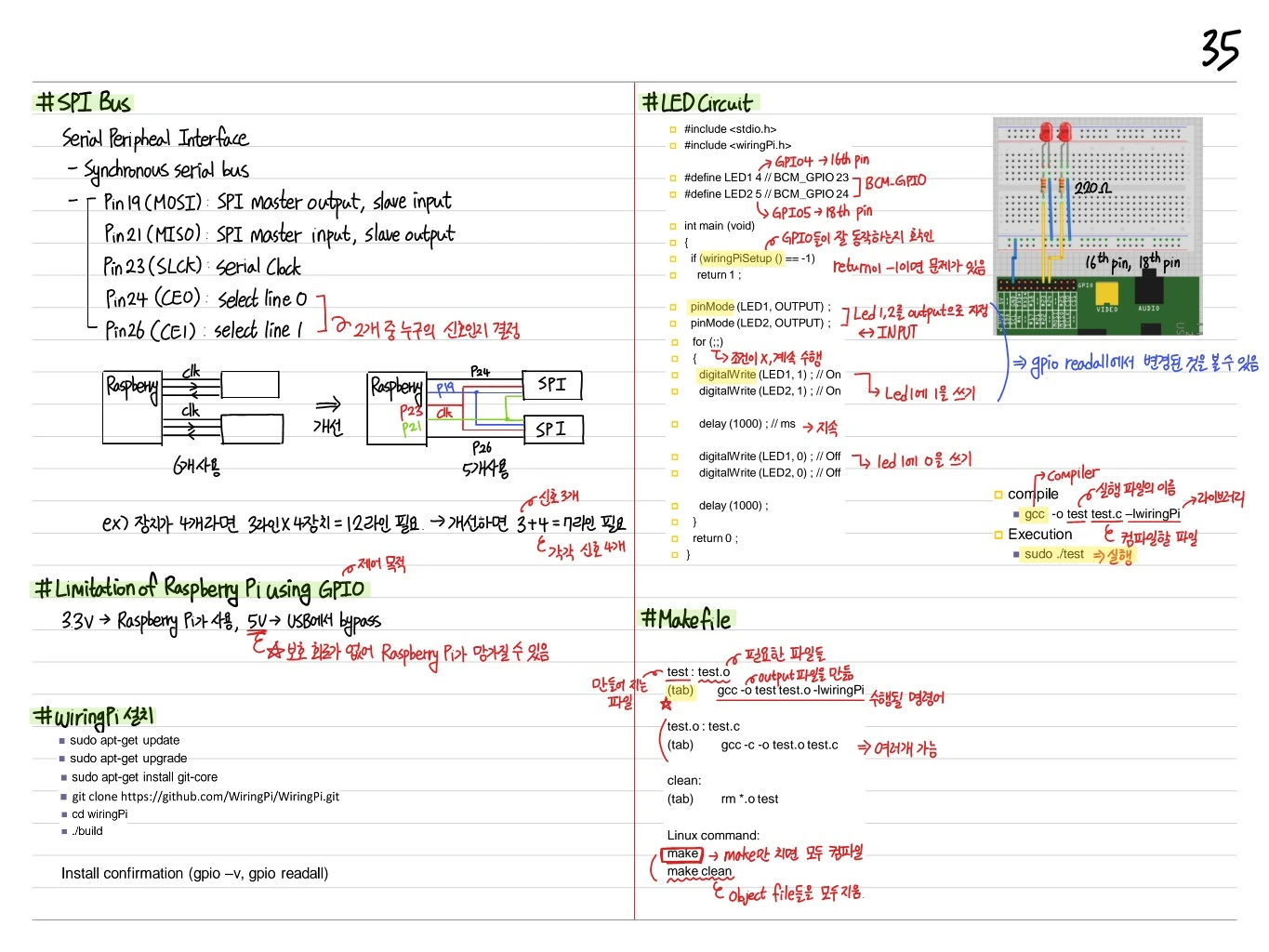
BCM2835 ARM Peripherals
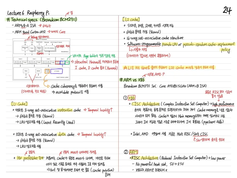
The peripheral register layout of the Broadcom BCM2835 (the Raspberry Pi's SoC):
- Peripheral addressing: physical addresses (PA) at a specific offset map to the peripheral registers
- ARM physical address: within 0x00000000–0xFFFFFFFF, the peripheral region is in the 0x20000000 range
GPIO Bus Address Layout
- BCM2835: GPIO base =
0x20200000(Raspberry Pi 1) /0x3F200000(Raspberry Pi 2/3) - Each GPIO function register is placed at an offset from the base
Register View
| Address | Register | Description |
|---|---|---|
| 0x20200000 | GPFSEL0 | Function Select pins 0-9 |
| 0x20200004 | GPFSEL1 | Function Select pins 10-19 |
| 0x20200020 | GPSET0 | Pin Output Set 0 |
| 0x2020002C | GPCLR0 | Pin Output Clear 0 |
| ... | ... | ... |
- GPFSEL: pin function (input/output/alternate)
- GPSET: set pin HIGH
- GPCLR: clear pin to LOW
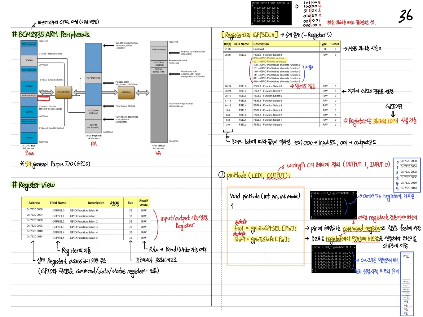
Register Map (GPFSEL x)
Each GPFSEL register uses 10 pins × 3 bits = 30 bits to set pin functions.
- 000 = Input
- 001 = Output
- 010–111 = Alternate function (UART, I2C, SPI, etc.)
pinMode Function
void pinMode(uint8_t pin, uint8_t mode) {
    uint8_t gpfsel = pin / 10;
    uint8_t offset = (pin % 10) * 3;
    uint32_t mask = 0b111 << offset;
    *(gpio + gpfsel) = (*(gpio + gpfsel) & ~mask) | (mode << offset);
}
Example: to set pin 4 as an output, write 001 to bits [14:12] of GPFSEL0.
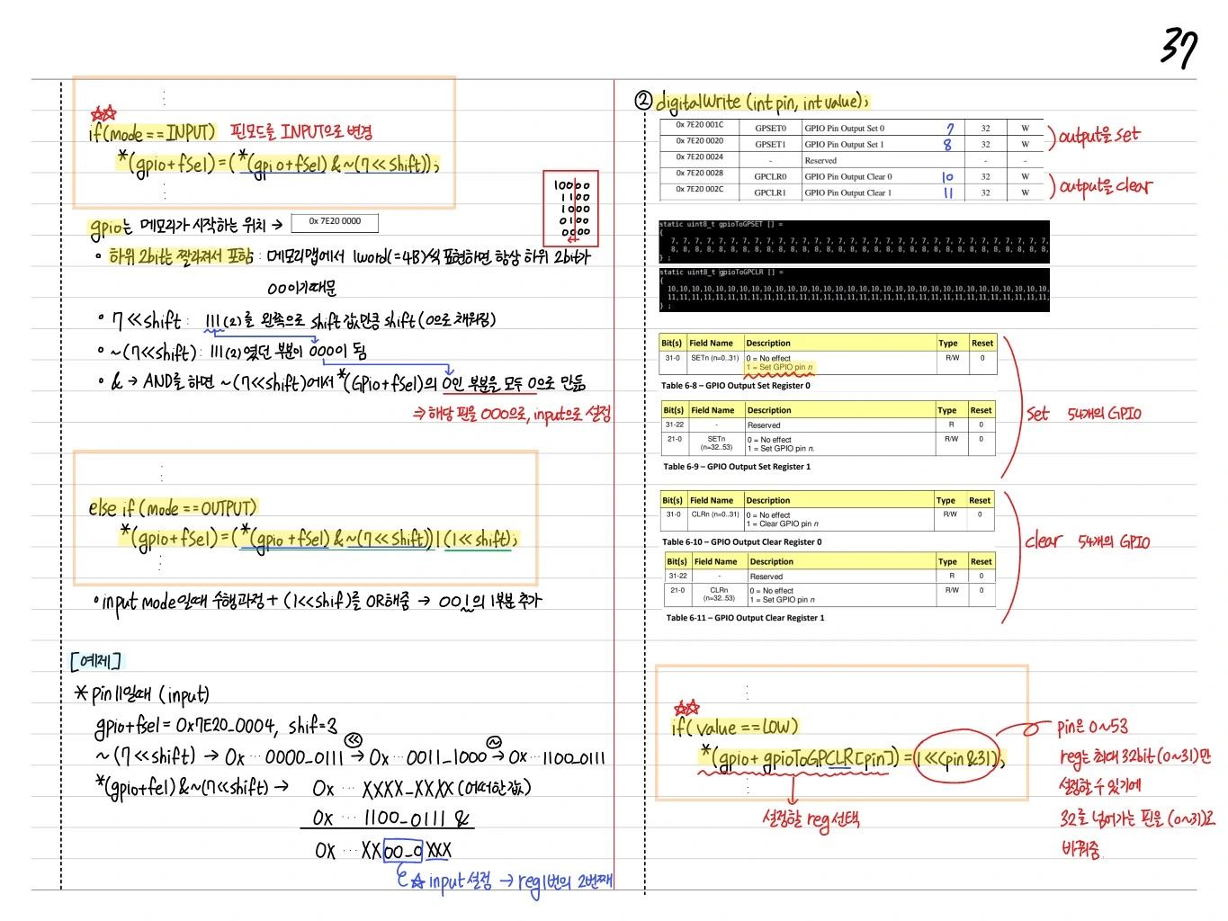
digitalWrite Function — Example
if (value == HIGH)
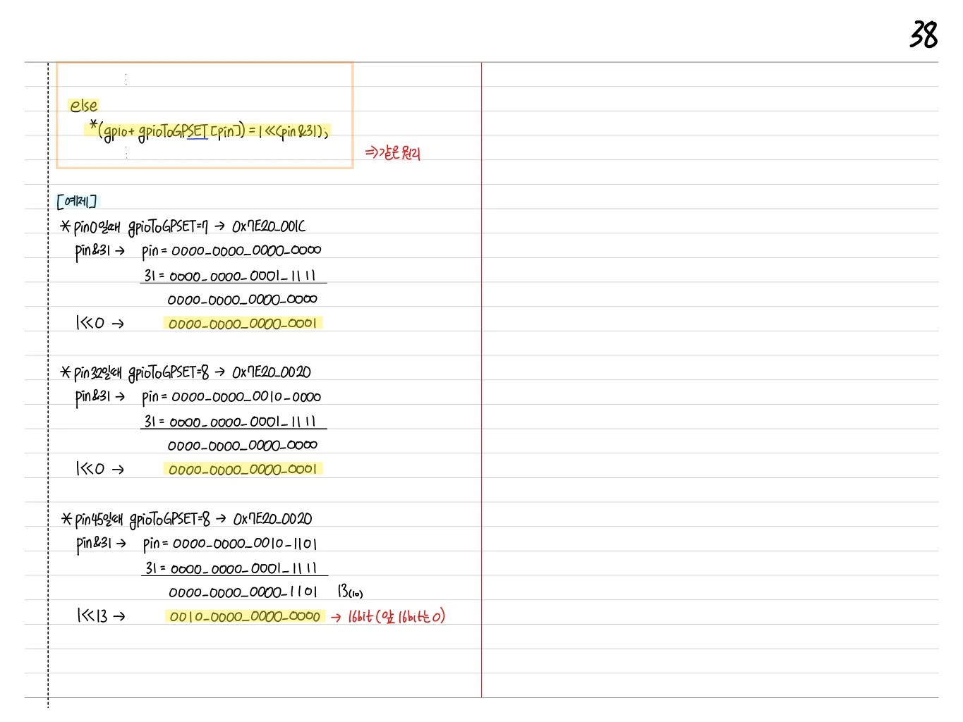
    *(gpio + gpioToGPSET[pin]) = 1 << (pin & 31);
else
    *(gpio + gpioToGPCLR[pin]) = 1 << (pin & 31);
Implemented on the same principle (GPSET and GPCLR work alike).
Example: computing the value for each pin
-
For pin 0, gpioToGPSET = 7 → 0x7E20_001C
pin & 31→pin = 0000_0000_0000_0000,31 = 0000_0000_0001_1111→ AND =0000_0000_0000_00001 << 0→0000_0000_0000_0001
-
For pin 32, gpioToGPSET = 8 → 0x7E20_0020
pin & 31:pin = 0000_0000_0010_0000,31 = 0000_0000_0001_1111→ AND =0000_0000_0000_00001 << 0→0000_0000_0000_0001
-
For pin 45, gpioToGPSET = 8 → 0x7E20_0020
pin & 31:pin = 0000_0000_0010_1101,31 = 0000_0000_0001_1111→ AND =0000_0000_0000_1101= 13 (decimal)1 << 13→0010_0000_0000_0000(16-bit; the upper 16 bits are 0)
Summary
| Interface | Key point |
|---|---|
| GPIO | Digital I/O, 3.3V reference, 40 pins |
| UART | Asynchronous, 2 wires (TX/RX) |
| I2C | 2 wires (SDA/SCL), master-slave |
| SPI | 4 wires (MOSI, MISO, SCLK, SS), high-speed |
| BCM2835 | Peripheral registers are memory-mapped |
| GPFSEL / GPSET / GPCLR | pin function, set high, clear |
Controlling the Raspberry Pi's GPIO directly at the hardware level laid the groundwork for my later work on embedded SoCs (Cortex-M3, STM32).