Chapter 2: Organization & Implementation Overview
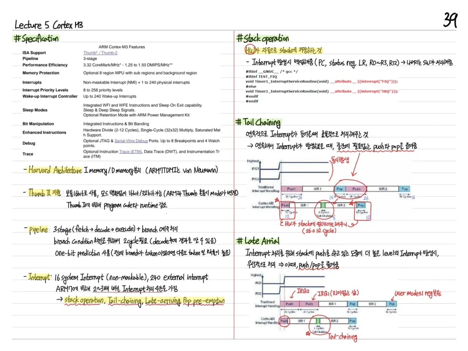
This chapter studies the organization and implementation of ARM processors. It covers the evolution from the 3-stage pipeline ARM to the 5-stage ARM9, the principal components, data forwarding, branches, and the memory bottleneck.
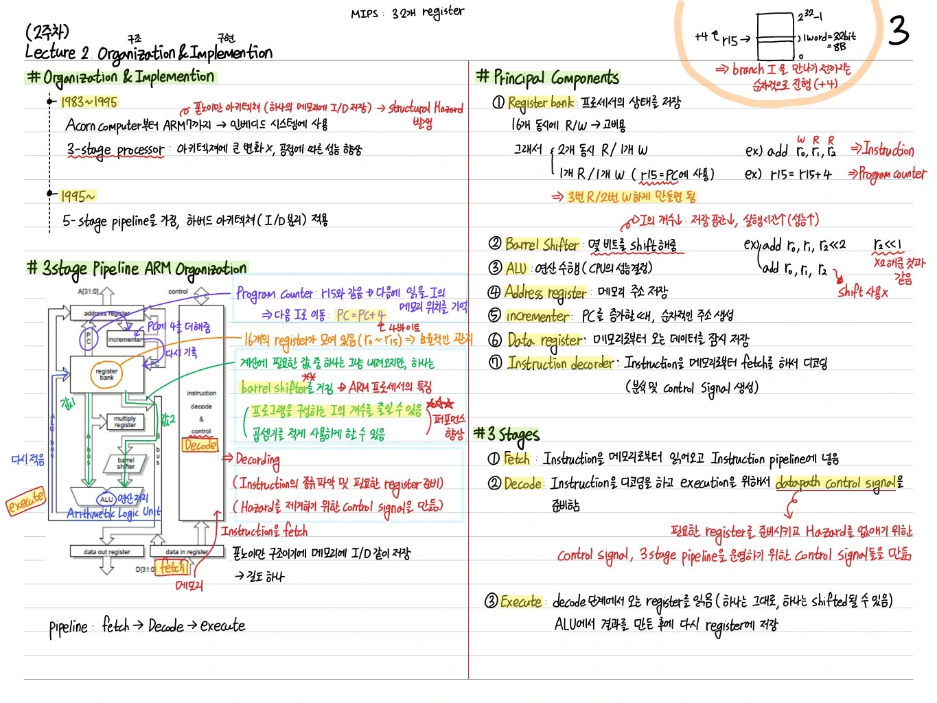
ARM's Principal Components
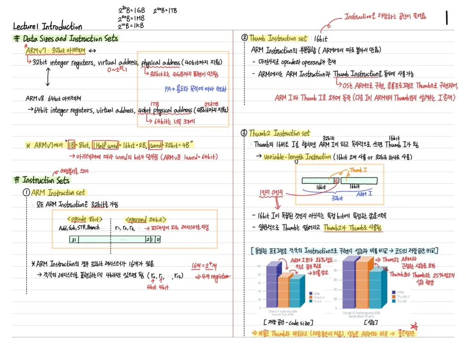
- Register file: sixteen 32-bit general-purpose registers. Some have fixed roles, such as the PC (R15) and LR (R14)
- Barrel shifter: shifts/rotates a register value within a cycle (an ARM feature)
- ALU: Arithmetic & Logic Unit
- Address register/incrementer: increments the PC for the next fetch
- Data register: holds data exchanged with memory
- Instruction register: the instruction currently executing
3-Stage Pipeline ARM (Up to ARM7)
Fetch → Decode → ExecuteEach stage takes one cycle, and the CPI is close to 1. The program counter is always the currently executing instruction + 8 (because of pipelining).
The 3 Stages
- Fetch: load the instruction into the instruction register → fetch complete
- Decode: interpret the instruction, read registers, generate control signals
- Execute: ALU operation, store the result in a register
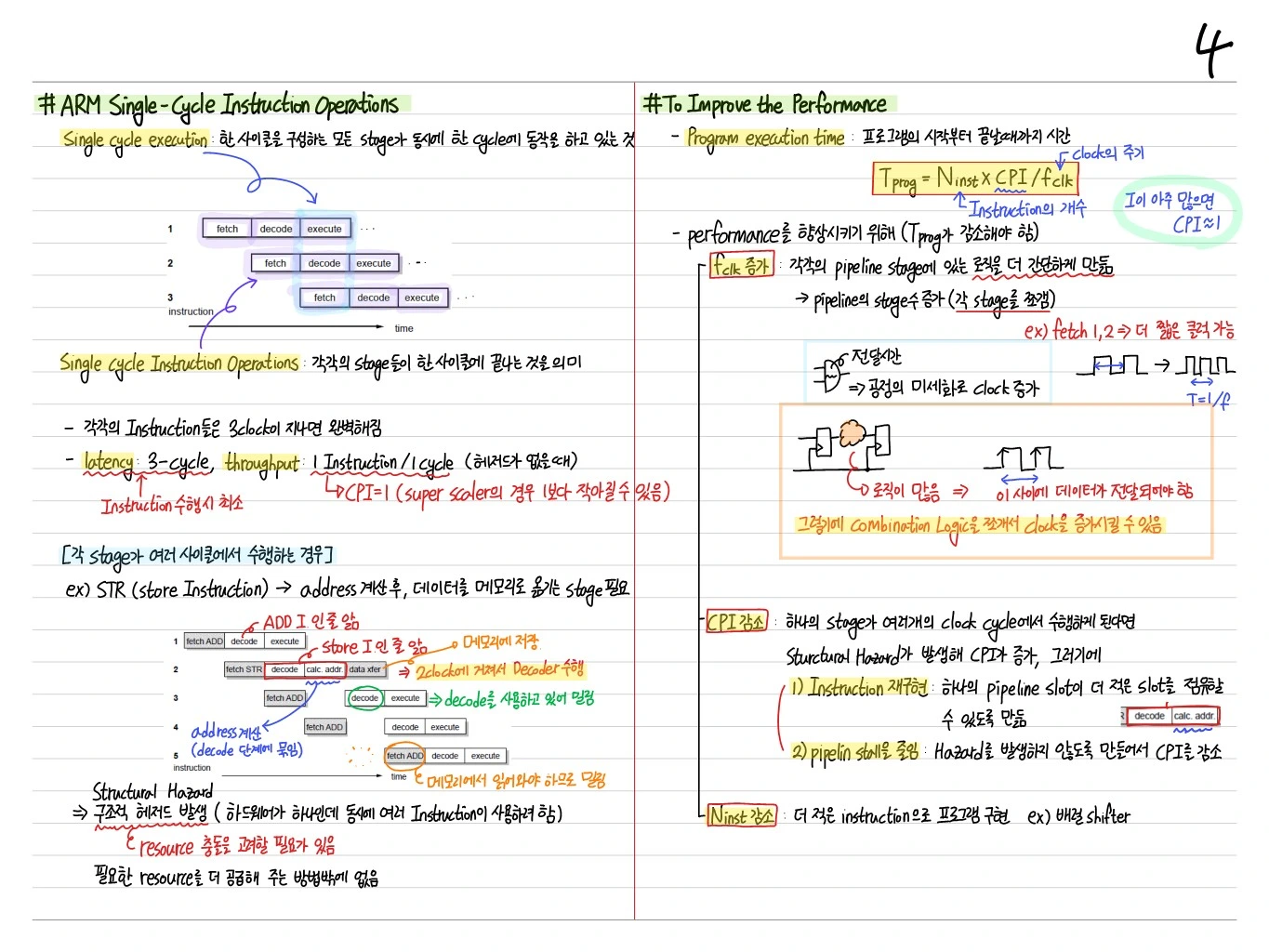
ARM Single-Cycle Instruction Operations
Kinds of ARM single-cycle instructions:
- Data operation: ALU operations such as ADD, SUB, MUL → stored in a register
- Addressing register R shifter: operations through the barrel shifter (an ARM feature)
- Store instruction: register value to memory (1 cycle)
STR (Store Instruction) — Address Mode 4, Writing with a Relative Address
Example: STR r0, [r1, #4] → store r0 at address r1 + 4
How to Improve the Performance
The basic formula for performance:
- : number of instructions (depends on the compiler and algorithm)
- : cycles per instruction (pipeline design)
- : clock period
→ Adding pipeline stages to shorten can improve performance, depending on pipeline efficiency. But hazards increase.
ARM expanded from a 3-stage to a 5-stage pipeline. With a faster clock and more pipeline stages, it ultimately built an efficient RISC-based pipeline.
Memory Bottleneck (Von Neumann Bottleneck)
- The memory bottleneck frequently causes structural hazards
- Reading an instruction and reading data cannot happen at the same time, so one has to stall → causes a hazard
Solution
Increase memory bandwidth:
- The usual approach: separate instruction and data memory (Harvard architecture)
- Each access needs to deliver more than 32 bits per cycle
5-Stage ARM Organization (ARM9)
Fetch → Decode → Execute → Buffer/Data → Write-Back- More stages → higher
- Separate instruction and data memory → 2x memory bandwidth
- CPI increases (more stages means more instructions overlap in flight)
- Hazards become more likely, but the other benefits outweigh this → higher , more memory bandwidth
The 5 Stages
- Fetch: read the instruction and put it into the pipeline
- Decode: identify the instruction type and prepare (registers, control signals)
- Execute: operand shift, ALU operation, address calculation
- Buffer/Data: memory access, or bypassed
- Write-Back: the result is stored in a register
Multiple Load/Store
A single instruction can replace several instructions → this is why there is a MUX section
LDR r1, 0(r0)    consecutive increments
LDR r1, 4(r0)    → can be replaced by one
LDR r1, 8(r0)
LDR r1, 12(r0)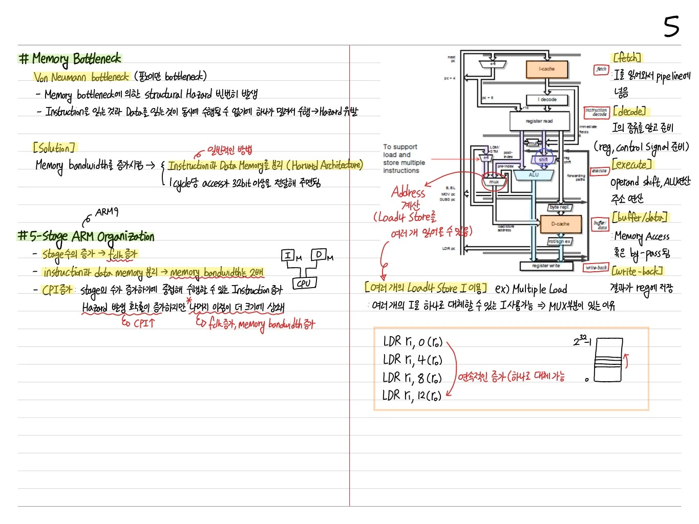
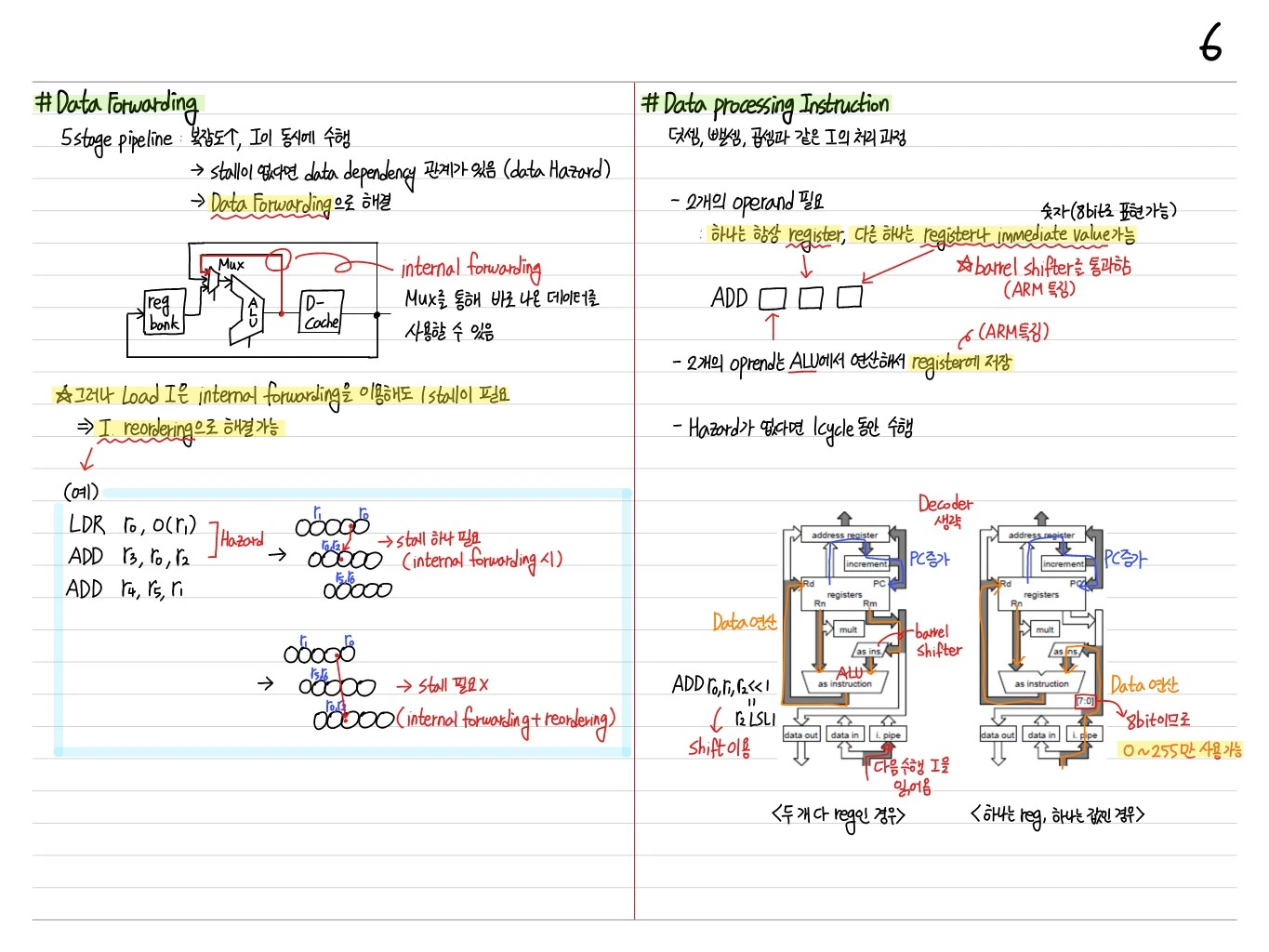
Data Forwarding
In a 5-stage pipeline, throughput goes ↑ and instructions execute concurrently.
- Without stalls, there are data dependencies (data hazards)
- Solved with data forwarding
reg bank → Mux → ALU → D-cache
              ↑     │
              └─────┘   internal forwarding
The Mux lets the pipeline use data as soon as it is produced.
The Case of Load Instructions
However, a load instruction still needs 1 stall even with internal forwarding. → This can be solved by instruction reordering.
Example:
LDR r0, 0(r1)          LDR r0, 0(r1)
ADD r3, r0, r2    →    ADD r4, r5, r1
ADD r4, r5, r1          ADD r3, r0, r2
   (needs 1 stall)          (no stall needed)
Data Processing Instruction
How instructions such as addition, subtraction, and multiplication are processed.
- Needs 2 operands
- One is always a register, and the other can be a register or an immediate value (expressible in 8 bits)
- Passes through the barrel shifter (an ARM feature)
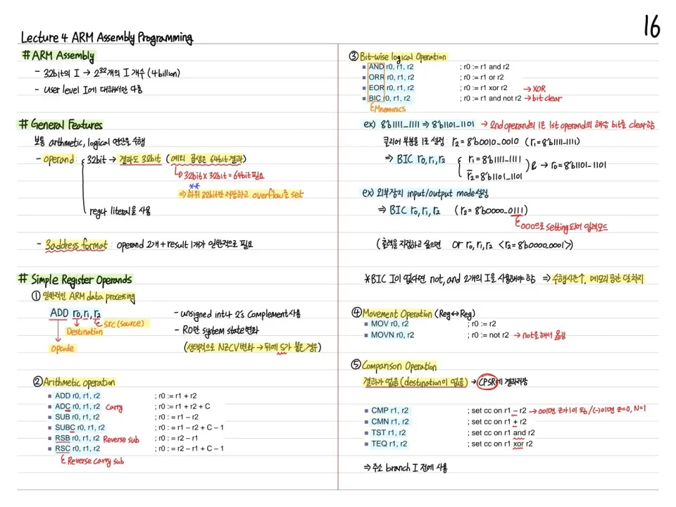
ADD [reg] [reg/imm] (with optional shift)- The 2 operands are computed in the ALU and stored in a register (an ARM feature)
- Executes in 1 cycle if there is no hazard
Example
ADD r0, r1, r2 << 1 ← r2 LSL 1 (using the shift)- Data operation: comes out on
data out - Decoder omitted
Data Transfer Instruction
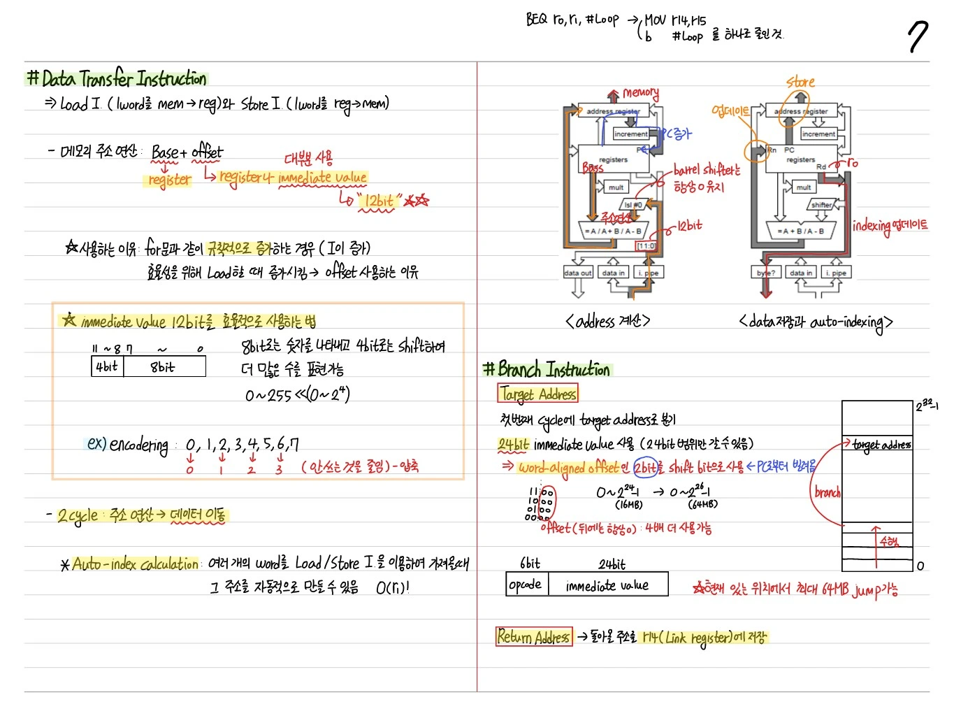
Moves data between memory and registers (load/store).
- Level 1 (load instruction) = single memory cycle: stage 1 (1-cycle register access)
- Reading data: register ← memory[address]
- Writing data: memory[address] ← register
Auto-Index (Pre/Post Index)
- Pre-index:
LDR r1, [r2, #4]→ address = r2 + 4, read from memory (r2 unchanged) - Pre-index with writeback:
LDR r1, [r2, #4]!→ address = r2 + 4, r2 = r2 + 4 (updated) - Post-index:
LDR r1, [r2], #4→ address = r2, then r2 = r2 + 4 after the read
This supports ARM's distinctive load/store with auto-indexing.
Single Instruction → Auto-Index Calculation
ARM handles address calculation efficiently with auto-indexing during load/store. Other ISAs need a load + add, but ARM does it in one instruction.
Branch Instruction
PC-relative addressing and target address calculation.
- Compute a signed offset relative to the PC → target address
- Target address = PC + offset
Simple branch (B label):
- 1st cycle: compute the target and update the PC
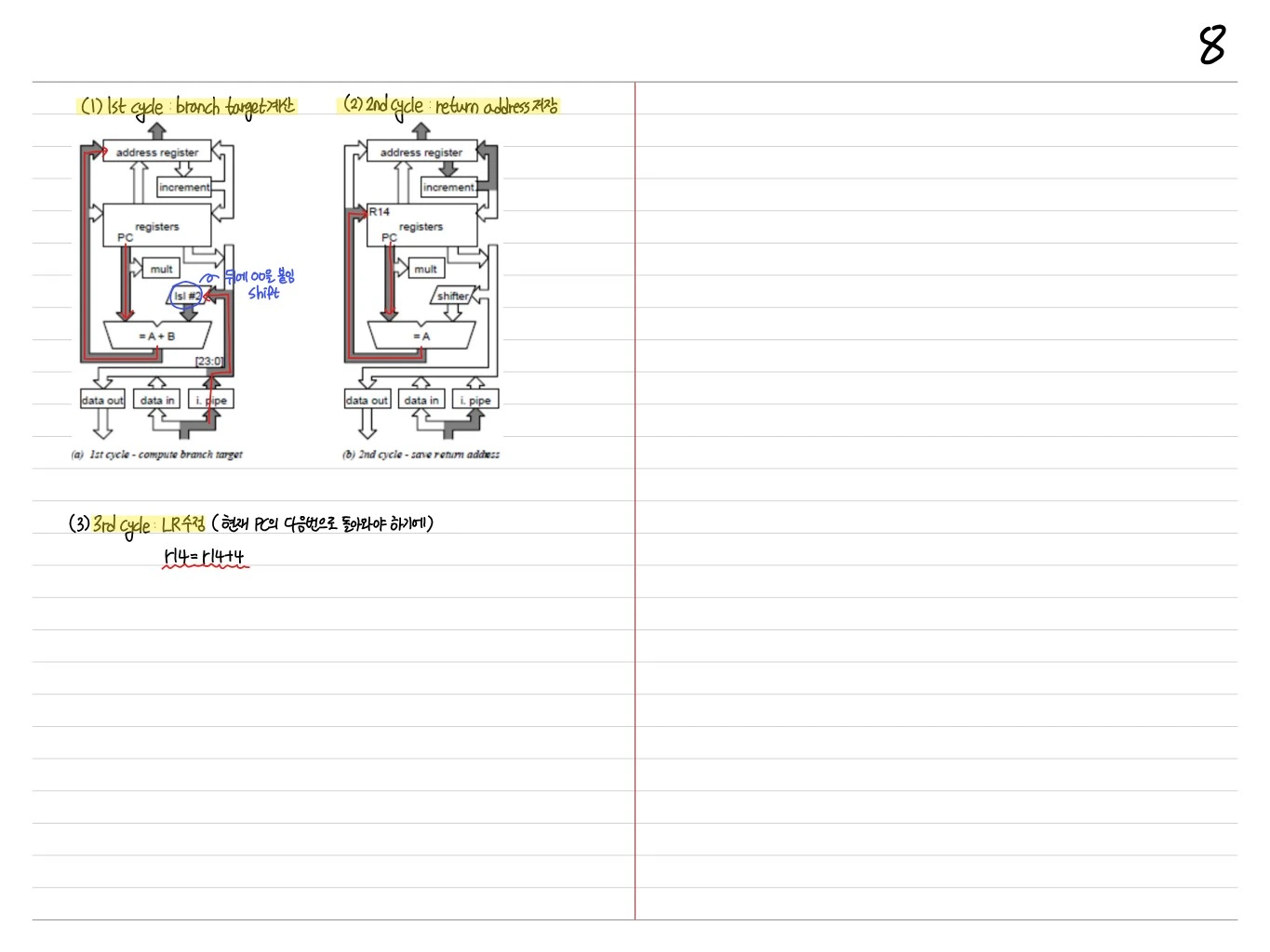
Branch with Link (BL label):
- 1st cycle: compute the branch target
- 2nd cycle: save the return address in R14 (LR)
- 3rd cycle: adjust LR (it must return to the instruction after the current PC) → R14 = R14 + 4
Summary
- Principal components: register file, barrel shifter, ALU, address/data registers, instruction register
- Evolved from 3-stage (ARM7) → 5-stage (ARM9): higher + 2x memory bandwidth with a Harvard architecture
- Data forwarding: internal forwarding through a Mux resolves most data hazards; load-use needs 1 stall or reordering
- Data processing instructions: pass through the barrel shifter, 2 operands (one can be an immediate), ALU result stored in a register
- Data transfer instructions: auto-indexing (pre/post) makes address calculation efficient
- Branch: PC-relative; BL takes 3 cycles (target + save LR + adjust LR)
By combining the basic principles of pipelining with ARM-specific optimizations (barrel shifter, auto-indexing, multiple load/store), ARM realizes the essence of RISC.