Chapter 5 overview: Storage and Other I/O Topics
In a computer system, I/O refers to every device that exchanges data with the outside world, such as disks, networks, and graphics. This chapter covers the basic concepts of I/O, dependability, the interrupt/polling/DMA transfer methods, and RAID configurations.
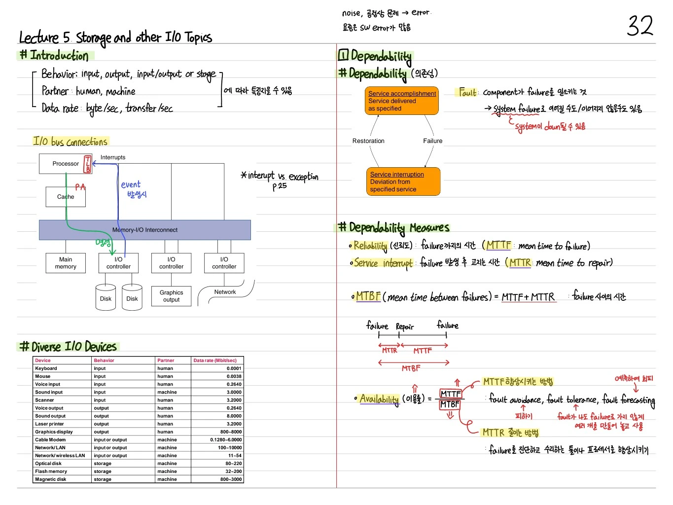
Introduction
I/O devices are characterized along three axes.
- Behavior: input, output, input/output, or storage
- Partner: human, machine
- Data rate: byte/sec, transfer/sec
I/O Bus Connections
[Processor]───[TLB / PA / Cache]
      │
[Memory-I/O Interconnect]
      │
┌─────┼─────┬──────┬─────────┐
Main  I/O    I/O    I/O
memory controller  controller controller
      │     │      │
     Disk  Graphics  Network
          output
When an event occurs, an interrupt is delivered to the processor.
Diverse I/O Devices (data rate comparison)
| Device | Behavior | Partner | Data rate (Mbit/sec) |
|---|---|---|---|
| Keyboard | input | human | 0.0001 |
| Mouse | input | human | 0.0038 |
| Voice input | input | human | 0.2640 |
| Sound input | input | machine | 3.0000 |
| Graphics display | output | human | 800~8000 |
| Network/LAN | input/output | machine | 100~10000 |
| Optical disk | storage | machine | 80~220 |
| Flash memory | storage | machine | 32~200 |
| Magnetic disk | storage | machine | 800~3000 |
Dependability
The ability of a system to reliably deliver its specified service. A system moves back and forth between the following two states.
Service accomplishment ↔ (Failure / Restoration) ↔ Service interruption
(specified service) (deviation from specified)- Fault: a component failing → it may or may not lead to a system failure. The system can go down.
- Noise and manufacturing defects → errors. Most of them are SW errors.
Dependability Measures
- Reliability: time until failure → MTTF (Mean Time To Failure)
- Service interruption: time to repair after a failure → MTTR (Mean Time To Repair)
- MTBF (Mean Time Between Failures) = MTTF + MTTR (time between failures)
- Availability:
Improving MTTF: anticipate and avoid
- Fault avoidance: avoid faults
- Fault tolerance: keep a fault from turning into a failure (build several copies and use them, i.e. redundancy)
- Fault forecasting: predict faults
Reducing MTTR
Improve the tools and processes for diagnosing and repairing failures.
I/O Management
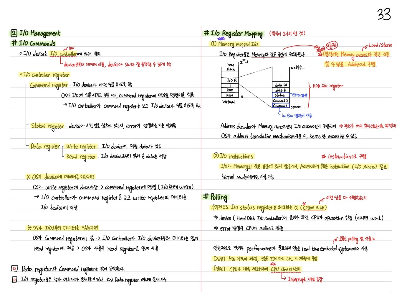
I/O Commands: I/O Controller Registers
Each I/O device has a command register, status register, and data register. The CPU controls the device by reading and writing these registers.
- Command register: tells the I/O controller what to do
- Status register: whether the I/O has completed, whether an error occurred, etc.
- Data register: the data being exchanged (read/write)
I/O Register Mapping
The I/O controller registers are mapped into the memory address space so that I/O is controlled with ordinary load/store instructions. This is called memory-mapped I/O.
- Memory and I/O registers share the same address space
- Reduces the complexity of the CPU interface
Polling
The CPU periodically checks the status register to see the state of the I/O device.
- Pro: simple to implement
- Con: wastes CPU resources (the CPU can't do other work)
Interrupts
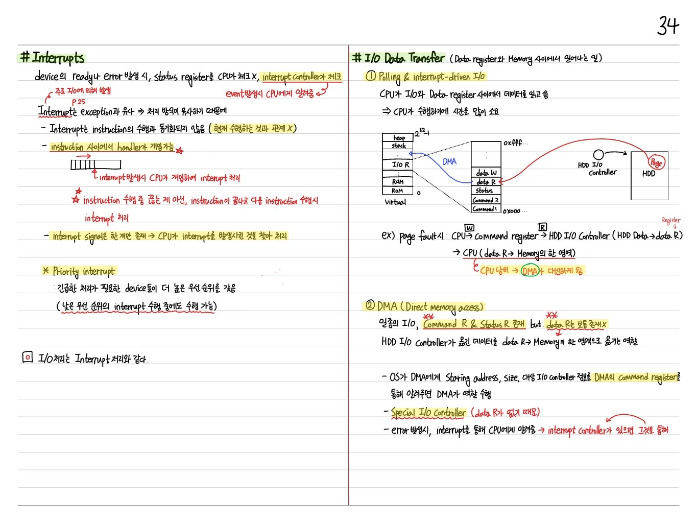
When a device becomes ready or an error occurs, the CPU does not check the status register; the interrupt controller does. It notifies the CPU when an event occurs.
Interrupt vs Exception
Interrupts are similar to exceptions (because they are handled in a similar way). They are mainly caused by I/O.
- Interrupts are not synchronized with instruction execution (unrelated to what is currently executing)
- The handler can step in between instructions (the interrupt is handled not by cutting off an instruction mid-execution but after the instruction finishes, before the next one executes)
- There is only one interrupt signal → the CPU finds what raised the interrupt and handles it
Priority Interrupt
Devices that need urgent handling have higher priority. They can be serviced even while a lower-priority interrupt is being handled.
I/O handling is the same as interrupt handling.
I/O Data Transfer (what happens between the data register and memory)
① Polling & Interrupt-Driven I/O
The CPU reads and writes data between the I/O device's data register and memory → this consumes a lot of CPU time.
Example: on a page fault, CPU → command register → HDD I/O controller (HDD data → data R) → CPU (data R → a region of memory). This wastes the CPU → it is replaced by DMA.
② DMA (Direct Memory Access)
A kind of I/O device with a command R and status R, but usually no data R.
It moves the data read by the HDD I/O controller from data R to a region of memory.
- The OS gives the DMA the starting address, size, and target I/O controller through the DMA's command register, and the DMA does the work
- A special I/O controller (because it has no data R)
- On an error, it notifies the CPU with an interrupt → through the interrupt controller if there is one
DMA and Cache/VM Interaction
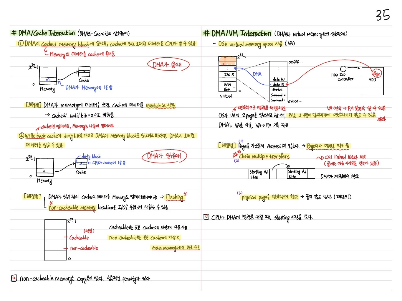
DMA/Cache Interaction
When the DMA reads a cached location, memory may not be up to date (dirty in the cache) → the cache must be flushed.
- The DMA writes to a cached location → the copy in the cache is stale (must be invalidated)
- Flushing is needed so cached locations aren't read incorrectly
Solutions
- Flush the physical memory region before the DMA starts (write dirty data in the cache back to memory)
- After the DMA finishes, invalidate (invalidate stale copies in the cache)
- The region can also be marked non-cacheable
DMA/VM Interaction
In an OS virtual memory environment, the DMA operates on physical addresses.
- One VM page can span multiple frames → the DMA must split transfers by page
- Use multiple handlers / process physical pages in several separate pieces
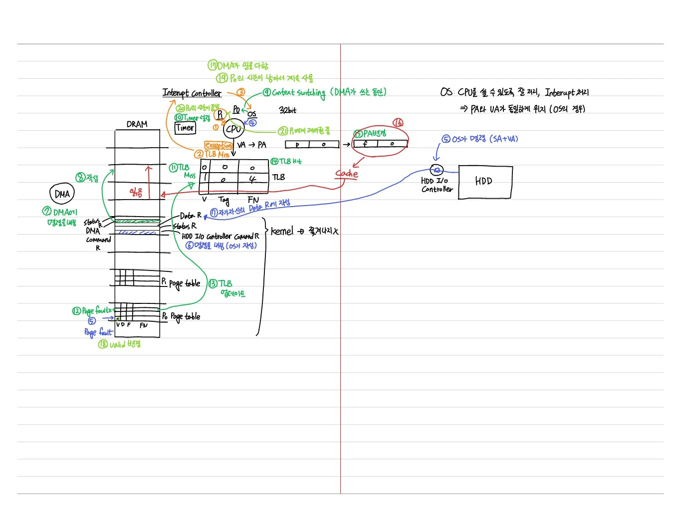
Full scenario: DMA during program execution
Below is the full flow with two processes, P0 and P1, running while the DMA performs I/O:
- P0 runs → timer is set
- TLB miss → exception → TLB update
- Page fault → command sent to the DMA
- The OS writes the command to the DMA command register (kernel → not preempted)
- Context switch while the DMA works (P0 → P1)
- P1 runs (TLB misses occur, but the data is in DRAM, so it keeps running)
- The DMA finishes → the interrupt controller notifies the OS
- P1 still has time left, so it keeps running
- P1's time slice ends and control goes to P0 → TLB hit → PA translation → cache → data used
- The OS issues a command (SA+VA) → HDD I/O controller → HDD
In this way, the DMA, timer, TLB, page table, and cache all work together.
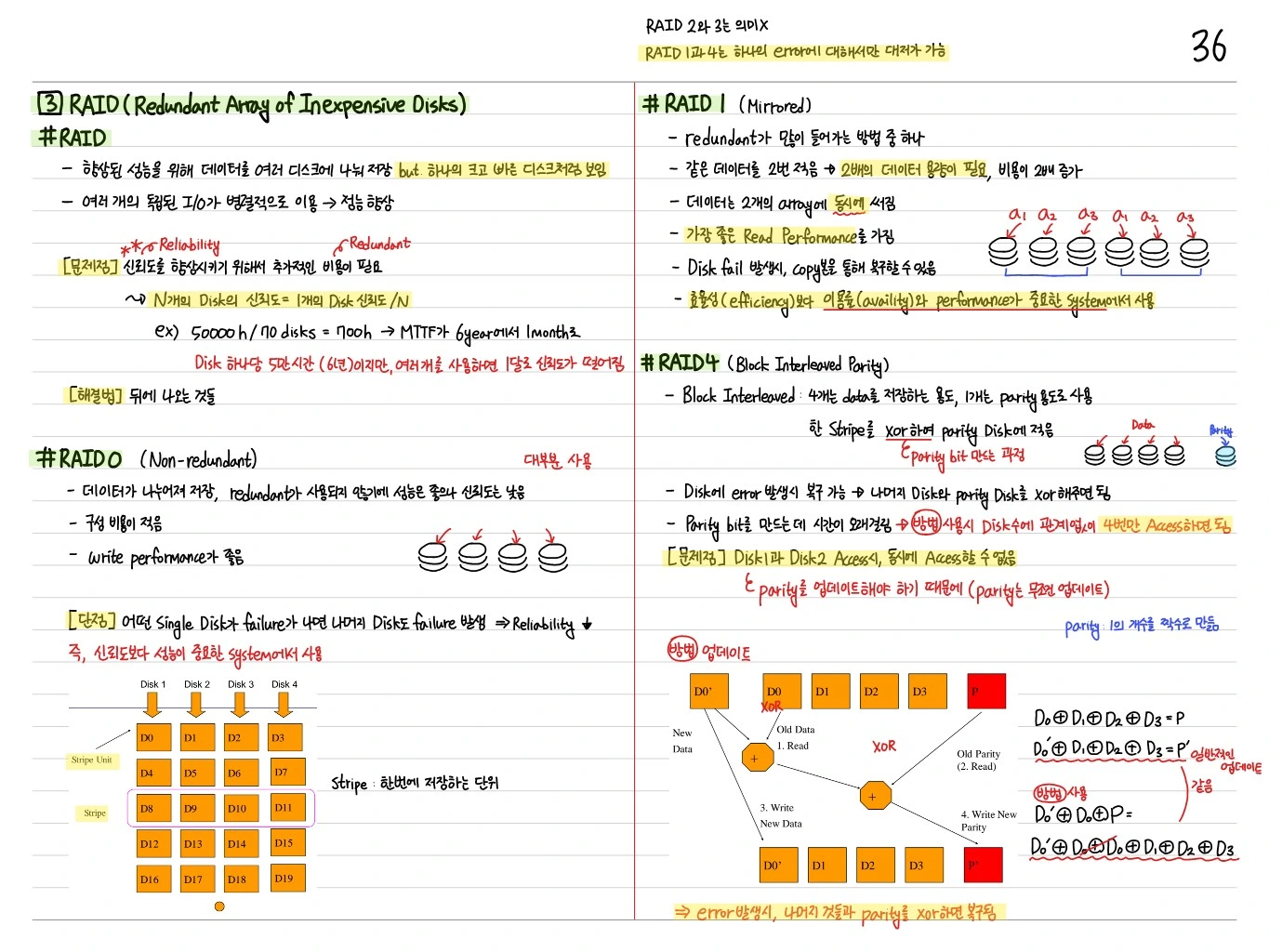
RAID (Redundant Array of Inexpensive Disks)
A technique that groups multiple disks to get reliability + performance at the same time.
RAID 0 (Striping)
- Data is split across multiple disks (striped)
- Pro: higher performance (parallel reads/writes)
- Con: no redundancy → if one disk fails, data is lost
RAID 1 (Mirroring)
- The same data is copied to two disks
- Pro: higher reliability (if one fails, the other is used)
- Con: half the capacity, higher cost
RAID 2, 3 (older RAID levels)
- Bit-level / byte-level parity (rarely used)
RAID 4 (Block-Interleaved Parity)
- Block striping + one separate parity disk
- Reads can be parallel, but the parity disk is a bottleneck for writes
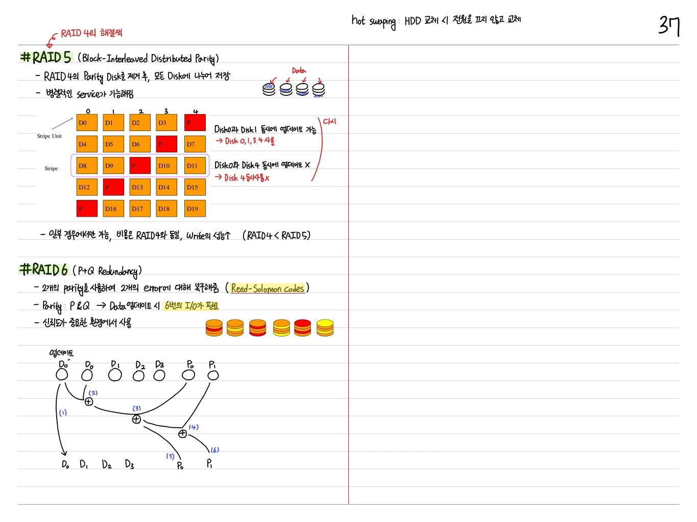
RAID 5 (Block-Interleaved Distributed Parity)
- Removes RAID 4's parity disk and distributes parity across all disks
- Enables parallel service
- Possible only in some cases; same cost as RAID 4, better write performance (RAID 4 < RAID 5)
Example:
      0    1    2    3    4
Stripe Unit D0  D1  D2  D3  P
           D4  D5  D6  P   D7
           D8  D9  P   D10 D11
           D12 P   D13 D14 D15
P D16 D17 D18 D19- Disk 0 and disk 1 can be updated at the same time → uses disks 0, 1, 3, and 4
- Disk 0 and disk 4 cannot be updated at the same time (parity conflict) → disk 4 can't be used twice
RAID 6 (P+Q Redundancy)
- Uses two parities to recover from two errors (Reed-Solomon codes)
- Parity P & Q → a data update requires 6 I/Os
- Used where reliability is critical
Hot swapping: replacing an HDD without turning off the power.
Summary
| Concept | Key point |
|---|---|
| Dependability | Reliability, Availability — MTTF/MTTR/MTBF |
| Polling | CPU periodically checks the status register |
| Interrupt | Signal to the CPU on a device event |
| DMA | Direct memory-I/O transfer without the CPU |
| RAID 0 | Striping — higher performance |
| RAID 1 | Mirroring — higher reliability |
| RAID 5 | Distributed parity — balance of performance and reliability |
| RAID 6 | P+Q redundancy — tolerates 2 faults |
From the CPU's point of view, I/O is much slower than memory access, so the keys are asynchronous techniques that keep the CPU as busy as possible (interrupts, DMA) and reliability through multiple disks (RAID).