Chapter 9: SoC Programming Using C Overview
The basic approach to programming an embedded SoC in C. Covers peripheral access through memory-mapped I/O, pointer manipulation, the volatile keyword, bit operations, the startup sequence, linker scripts, and more.
Memory-Mapped I/O
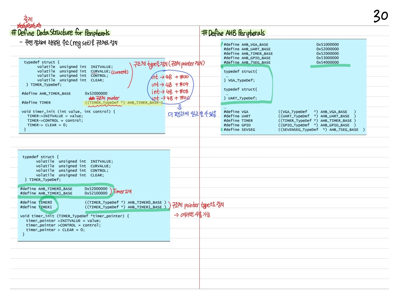
On ARM Cortex-M, every peripheral is mapped to a specific memory address. Accessing a register = reading/writing that address.
#define GPIO_ODR (*(volatile uint32_t *)0x40020014)

GPIO_ODR = 0x01;   // set GPIO output
uint32_t val = GPIO_ODR;  // read current state
volatile Keyword
- Prevents compiler optimization (e.g. it must not skip reading the same address twice)
- Hardware registers can change from the outside, so they must be volatile
volatile uint32_t *GPIO_IDR = (volatile uint32_t *)0x40020010;
while (!(*GPIO_IDR & 0x1)) ;  // wait until the button is pressed
Without volatile, the compiler optimizes the loop and it waits forever.
Struct-Based Register Access
Large peripherals are defined as structs (CMSIS style):
typedef struct {
    volatile uint32_t MODER;    // 0x00
    volatile uint32_t OTYPER;   // 0x04
    volatile uint32_t OSPEEDR;  // 0x08
    volatile uint32_t PUPDR;    // 0x0C
    volatile uint32_t IDR;      // 0x10
    volatile uint32_t ODR;      // 0x14
    // ...
} GPIO_TypeDef;

#define GPIOA ((GPIO_TypeDef *)0x40020000)

GPIOA->ODR = 0x01;
Bit Operations
Bit Set
GPIOA->ODR |= (1 << 5); // set bit 5 to 1Bit Clear
GPIOA->ODR &= ~(1 << 5); // set bit 5 to 0Bit Toggle
GPIOA->ODR ^= (1 << 5); // invert bit 5Bit Check
if (GPIOA->IDR & (1 << 5)) { /* bit 5 is 1 */ }Multi-bit Field
Setting a 2-bit field to the value val:
GPIOA->MODER &= ~(0x3 << (pin * 2));    // clear 2 bits
GPIOA->MODER |= (val << (pin * 2));     // set value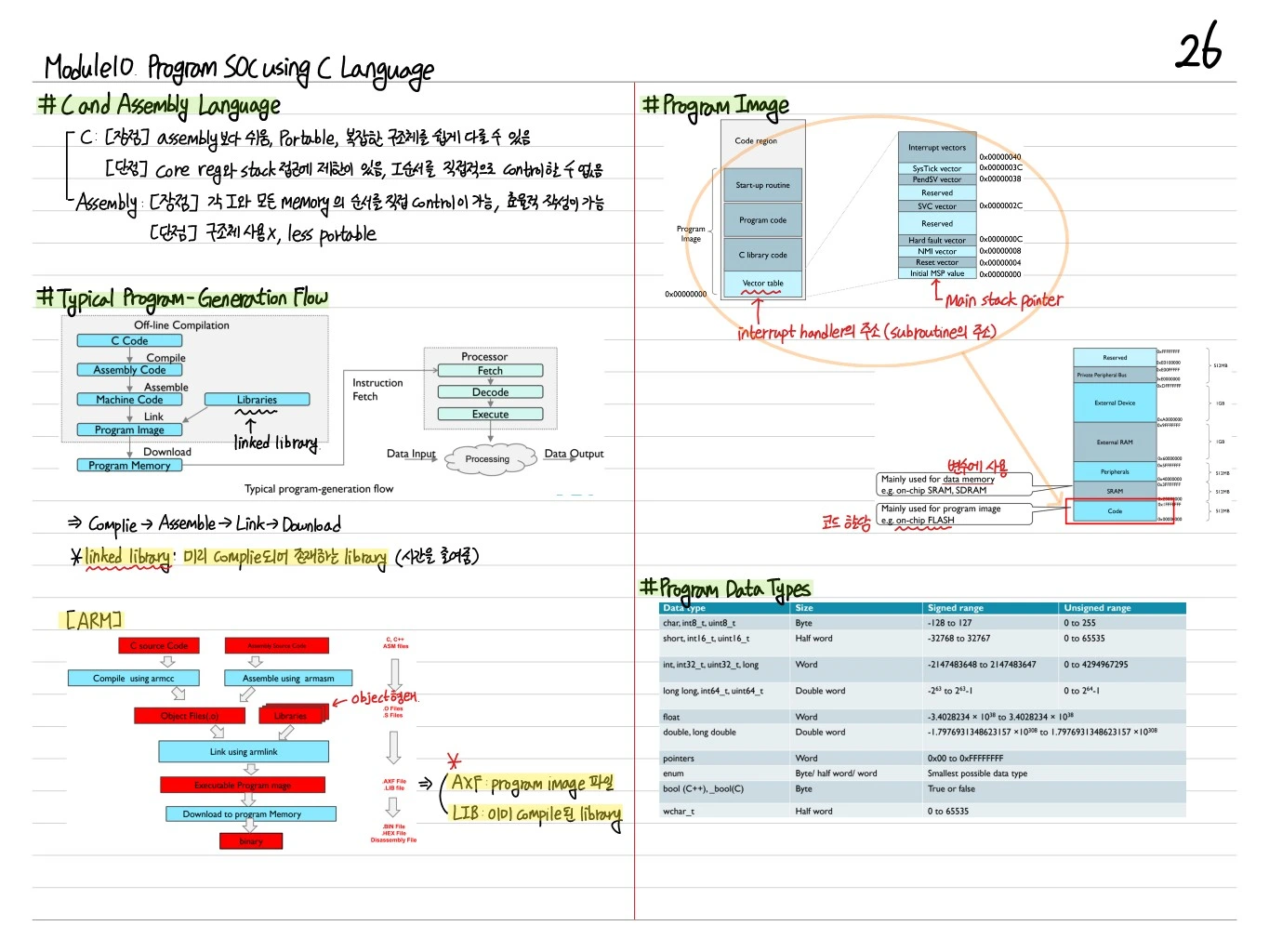
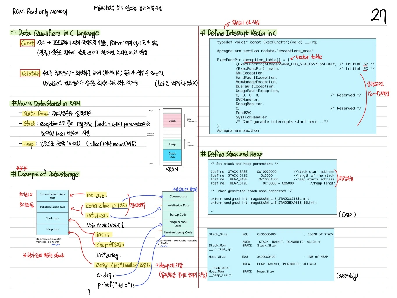
Startup Sequence
The initialization the processor performs on reset:
- R13 ← Initial SP (vector table offset 0x00)
- PC ← Reset handler (offset 0x04)
- Reset handler:
- Copy the
.datasection from Flash to RAM - Zero-initialize the
.bsssection - Call
SystemInit()(clock and PLL setup) - Call
main()
- Copy the
void Reset_Handler(void) {
    // Copy .data from Flash to RAM
    extern uint32_t _sdata, _edata, _sidata;
    uint32_t *src = &_sidata;
    uint32_t *dst = &_sdata;
    while (dst < &_edata) *dst++ = *src++;

    // Zero-init .bss
    extern uint32_t _sbss, _ebss;
    dst = &_sbss;
    while (dst < &_ebss) *dst++ = 0;

    SystemInit();
    main();
    while(1);
}
Linker Script
Defines the memory layout:
MEMORY {
    FLASH (rx) : ORIGIN = 0x08000000, LENGTH = 128K
    RAM (rwx)  : ORIGIN = 0x20000000, LENGTH = 20K
}

SECTIONS {
    .isr_vector : {
        KEEP(*(.isr_vector))
    } > FLASH

    .text : {
        *(.text*)
        *(.rodata*)
    } > FLASH

    .data : AT(_sidata) {
        _sdata = .;
        *(.data*)
        _edata = .;
    } > RAM

    .bss : {
        _sbss = .;
        *(.bss*)
        _ebss = .;
    } > RAM
}
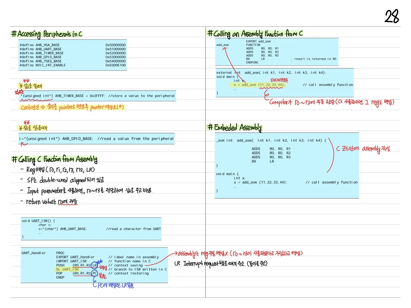
CMSIS (Cortex Microcontroller Software Interface Standard)
ARM's standard software interface:
- Core peripheral access (NVIC, SysTick, SCB)
- Vendor-specific register definitions
- DSP and NN libraries (optional)
Example:
#include "stm32f10x.h"    // CMSIS device header

int main(void) {
    RCC->APB2ENR |= RCC_APB2ENR_IOPCEN;   // GPIOC clock enable
    GPIOC->CRH = 0x00300000;              // PC13 output

    while (1) {
        GPIOC->ODR ^= (1 << 13);          // toggle LED
        for (volatile int i = 0; i < 100000; i++);  // delay
    }
}
Interrupt Handler
CMSIS generates the vector table automatically. Just write the handler and it gets connected:
void TIM2_IRQHandler(void) {
    if (TIM2->SR & TIM_SR_UIF) {
        TIM2->SR = ~TIM_SR_UIF;    // clear flag
        GPIOC->ODR ^= (1 << 13);   // toggle LED
    }
}
The linker script places the address of TIM2_IRQHandler at the corresponding offset in the vector table.
Clock Setup
An SoC's clock system is complex (HSI, HSE, PLL, AHB/APB prescalers).
void SystemInit(void) {
    // Enable HSE
    RCC->CR |= RCC_CR_HSEON;
    while (!(RCC->CR & RCC_CR_HSERDY));

    // Configure PLL
    RCC->CFGR = RCC_CFGR_PLLSRC | RCC_CFGR_PLLMULL9;
    RCC->CR |= RCC_CR_PLLON;
    while (!(RCC->CR & RCC_CR_PLLRDY));

    // Switch SYSCLK to PLL
    RCC->CFGR |= RCC_CFGR_SW_PLL;
}
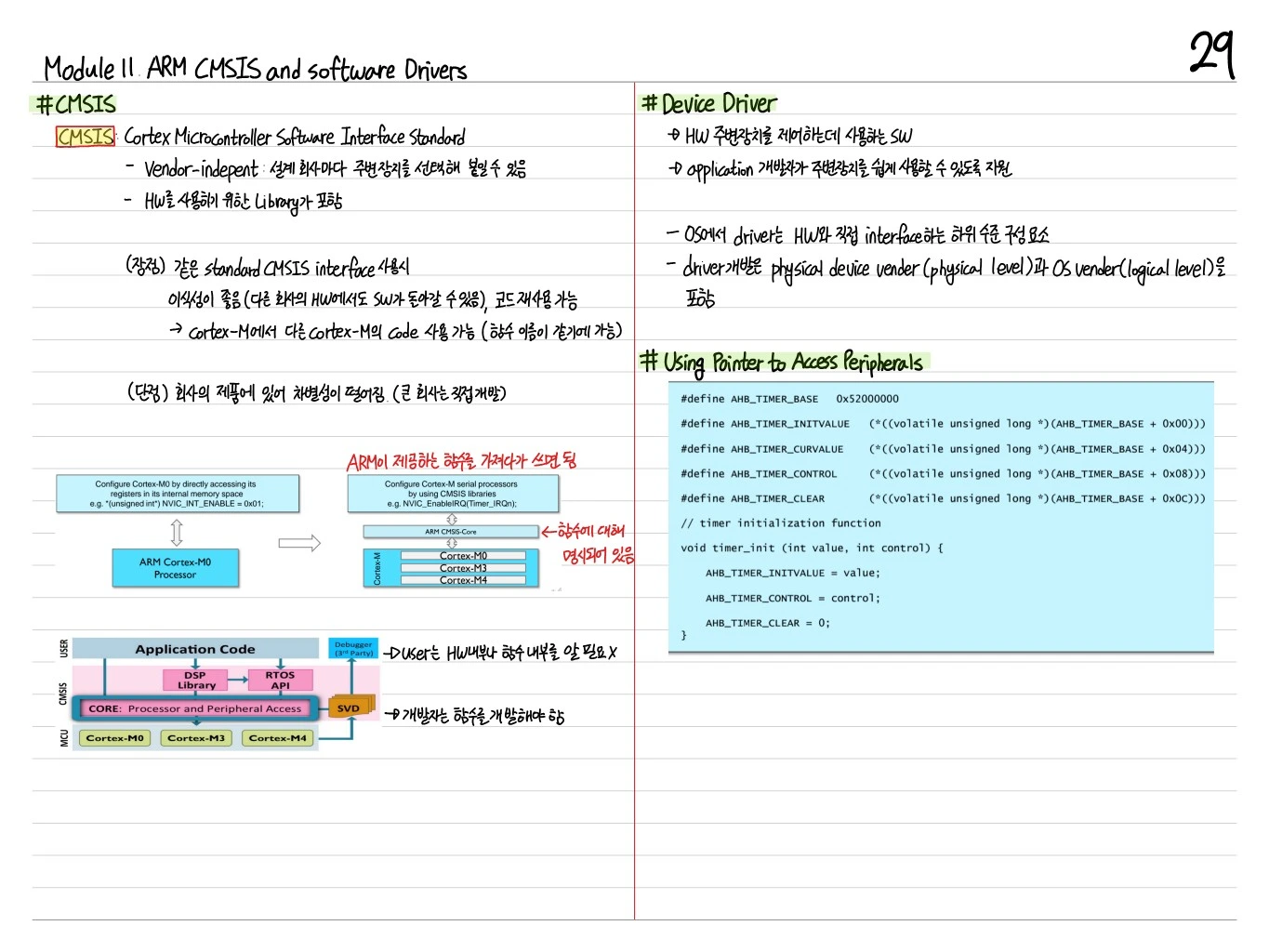
Debugging Tools
- printf via UART: Redefine
_write()insyscalls.c - Semihosting: stdout through the ARM debugger
- SWD (Serial Wire Debug): Breakpoints, watchpoints, live register view
- ITM (Instrumentation Trace Macrocell): High-speed trace
Optimization Tips
- Inline: Make short functions
static inline - Use volatile only where truly needed (it hinders optimization)
- Cache alignment: Align DMA buffers to cache lines
- -O2 / -Os: gcc optimization levels; in embedded, size matters
Summary
| Concept | Key Point |
|---|---|
| Memory-mapped I/O | Peripheral = address |
| volatile | Prevents compiler optimization |
| Struct access | Abstracts register groups |
| Bit op | Set/Clear/Toggle/Check |
| Startup | Vector table → Reset handler → main |
| Linker script | Defines the FLASH/RAM layout |
| CMSIS | ARM's standard software interface |
| Interrupt handler | C function + linker connection |
Programming an SoC in C means abstracting the hardware level with C pointers. Once you master volatile, structs, and bit operations, you can directly control any MCU.